Rotary lifting-type gear sleeve automatic high frequency quenching device

A technology of rotary lifting and high-frequency quenching, which is applied in the direction of quenching device, energy efficiency improvement, process efficiency improvement, etc., to achieve the effect of reducing labor intensity and improving production efficiency

Inactive Publication Date: 2012-03-21
ANHUI MINGYAN GEAR
View PDF5 Cites 43 Cited by
  • Summary
  • Abstract
  • Description
  • Claims
  • Application Information

AI Technical Summary

Problems solved by technology

In the current traditional high-frequency quenching process, the high-frequency quenching of the inner tooth surface of the gear sleeve mostly adopts the traditional high-frequency induction heating machine tool. Because the machine tool is operated in a manual operation environment, its radiation and high-intensity magnetic field are harmful to the operator. health hazard
The second is that the machine tool is expensive, the manufacturing cost is high, manual operation is required, labor intensity is high, and production efficiency is low, which limits its application in the production of gear sleeves.

Method used


Image

  • Rotary lifting-type gear sleeve automatic high frequency quenching device
  • Rotary lifting-type gear sleeve automatic high frequency quenching device
  • Rotary lifting-type gear sleeve automatic high frequency quenching device

Examples


Embodiment Construction

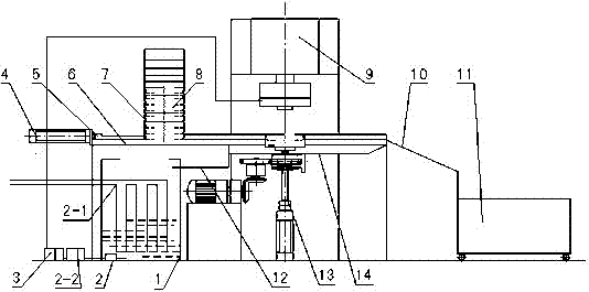
[0016] Pushing mechanism is made of pushing cylinder and pushing plate, and pushing cylinder 4 is installed on the end face of bed 6 one side, and the piston rod end of pushing cylinder is connected with pushing plate 5, and the other end of pushing plate is provided with A V-shaped groove that abuts against the outer circle of the workpiece in the bottom of the material storage rack 7 arranged in the left and right guide rail assemblies. The bed is a plane frame.

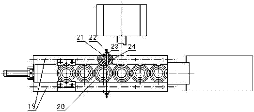
[0017] The left and right guide rail assemblies are composed of left and right guide rails, guide rail base plates, elastic fixing frames, elastic pin adjustment bolts, elastic pin springs and elastic pins. The guide rail base plate 20 is fixed on the end surface of the bed 6, and the left and right guide rails 19 are symmetrically installed on the guide rail base plate On the top, six trough stations are sequentially formed between the two guide rails along the advancing direction of the pushing plate 5 in the pus...


PUM


Abstract

The invention discloses a rotary lifting-type gear sleeve automatic high frequency quenching device, which is composed of a bed, a pushing mechanism, a left and right guide rails component, an automatic rotating and elevating component, high frequency induction quenching, a liquid cooling device, a discharging mechanism and PLC; a piston rod end of a pushing cylinder (4) arranged on an end-face at one side of the bed (6) is connected to a pushing plate (5), and the pushing plate (5) is supported against a workpiece circumcircle in a storing rack (7) arranged in the left and right guide rails component; elastic fixed mounts (21) are symmetrically arranged at the outboard of the left and right guide rails at a third material groove station formed between the left and right guide rails (19),a spring pin (24) passes through an adjusting bolt (22), a spring of the spring pin (23) and the left and right guide rails to form inner apertures which are supported against the workpiece circumcircle in the material groove station; a spline shaft controlled by a motor through a gear and a cylinder is provided at the lower part of a fourth material groove station, the end of the spline shaft isconnected with a workpiece positioning seat; a high frequency induction coil and a spray liquid loop supported by a coil pedestal and a cooling rack supporter are provided over the fourth material groove station. The rotary lifting-type gear sleeve automatic high frequency quenching device realizes the purposes of automatic quenching and cooling workpiece.

Description

technical field [0001] The invention relates to an automatic high-frequency quenching device of a rotating and lifting gear sleeve, which belongs to the technical field of processing machinery equipment. Background technique: [0002] The gear sleeve is an important power transmission part in mechanical equipment, and its application is extremely extensive. The high-frequency quenching of the inner tooth surface of the tooth sleeve is an effective means to obtain the hard tooth surface gear of the tooth sleeve, and it has a lower cost than carburizing and quenching and nitriding in the case of obtaining the corresponding hardness. In the current traditional high-frequency quenching process, the high-frequency quenching of the inner tooth surface of the gear sleeve mostly adopts the traditional high-frequency induction heating machine tool. Because the machine tool is operated in a manual operation environment, its radiation and high-intensity magnetic field are harmful to t...

Claims


Application Information

Patent Timeline
Patent Type & Authority Applications(China)
IPC IPC(8): C21D1/62C21D1/10C21D9/32
CPCY02P10/25
Inventor 胡少名周向东
Owner ANHUI MINGYAN GEAR
Why Eureka
Try Eureka