
Novel air-conditioning system

An air-conditioning system, air-conditioning technology, applied in the direction of air-conditioning system, space heating and ventilation, space heating and ventilation details, etc., can solve the problems of high cost, high use cost, volatile, etc., to ensure the service life and avoid refrigerant Effects of leakage and low running cost

Inactive Publication Date: 2012-03-21
ZHEJIANG YAONENG TECH
View PDF2 Cites 11 Cited by
  • Summary
  • Abstract
  • Description
  • Claims
  • Application Information

AI Technical Summary

Problems solved by technology

At present, in terms of cost, antifreeze is divided into two types: one is low-temperature antifreeze with a freezing point lower than -20°C, which has the advantages of low freezing point and low corrosion resistance, and the disadvantage of high cost and easy Volatile; the other is ordinary antifreeze with a freezing point of -10°C~-20°C, such as alkaline water, salt water, etc., which has the advantage of low cost and is not easy to volatilize. The disadvantage is that the freezing point is high and has a large Corrosive
If the low-temperature antifreeze is used directly, because the low-temperature antifreeze will have a large amount of volatilization during the cooling tower cycle, this will lead to a large amount of low-temperature antifreeze consumed, and the high cost of use is simply unbearable
However, if ordinary antifreeze is used, the strong corrosiveness of antifreeze will cause great damage to the evaporator coil, which will double the service life of the evaporator and easily cause refrigerant leakage.

Method used


Image

  • Novel air-conditioning system
  • Novel air-conditioning system
  • Novel air-conditioning system

Examples


Embodiment Construction

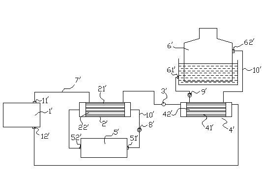
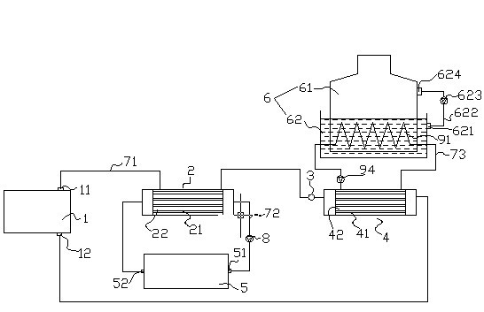
[0016] Such as figure 2 As shown, a novel air-conditioning system includes a compressor 1, a condenser 2, an expansion valve 3, an evaporator 4, an air-conditioning water tank 5, an air-conditioning water pump 8 and a cooling tower 6, wherein the condenser 2 is provided with a condenser coil 21 and the passage 22 outside the condenser coil, the evaporator 4 is provided with an evaporator coil 41 and an outside passage 42 of the evaporator coil. In the heating mode, the outlet 11 of the compressor → the passage 22 outside the condenser coil → the expansion valve 3 → the evaporator coil 41 → the inlet 12 of the compressor is connected in sequence with a common pipeline 71 to form a refrigerant circulation system. Air-conditioning water tank outlet 51→air-conditioning water pump 8→condenser coil 21→air-conditioning water tank inlet 52 are sequentially connected with air-conditioning pipeline 72 to form an air-conditioning water circulation system.

[0017] Described cooling tow...


PUM


Abstract

The invention discloses a novel air-conditioning system, comprising a compressor, a condenser, an expansion valve, an evaporator, an air-conditioning water tank, an air-conditioning pump and a cooling tower. The evaporator is provided with an evaporator coil and an evaporator coil outer passage. The cooling tower comprises a water curtain wall and a reservoir. The reservoir is provided with common antifreeze solution and simultaneously the reservoir is provided with a water outlet to form a common antifreeze solution circulating system through an anti-corrosion pipeline, an anti-corrosion pump and a water inlet at the upper part of the water curtain wall. The air-conditioning system further comprises an exchanger coil for carrying out heat exchange with common antifreeze solution out of the exchanger coil. The exchanger coil is connected with a low-temperature antifreeze solution circulating system injected with low-temperature antifreeze solution through a pipeline, a primary pump and the evaporator coil outer passage. The invention is designed by combining the low ice point advantage of the low-temperature antifreeze solution and low cost advantage of the common antifreeze solution, can normally work so long so the external temperature is higher than the ice point temperature of the common antifreeze solution, and be featured with low energy consumption, convenience, practicality and wide application scope.

Description

technical field [0001] The invention relates to a heat pump type water central air-conditioning system, in particular to a novel air-conditioning system. Background technique [0002] The existing heat pump water central air-conditioning system mainly includes a compressor 1', a condenser 2', an expansion valve 3', an evaporator 4', an air-conditioning water tank 5' and a cooling tower 6'. Here, under the heating condition, the compressor outlet 11'→the condenser coil passage 22'→the expansion valve 3'→the evaporator coil 41'→the compressor inlet 12' is sequentially connected by pipeline 7 'Connect to form a refrigerant circulation system; outlet 51' of the air-conditioning water tank→water pump 8'→coil 21' of the condenser→inlet 52' of the air-conditioning water tank are connected in sequence with pipeline 10' to form an air-conditioning water circulation system; cooling tower outlet 61'→water pump 9'→coil outer channel 42' of the evaporator→cooling tower inlet 62'are conn...

Claims


Application Information

Patent Timeline
IPC IPC(8): F24F5/00F24F13/30
Inventor 余小兵江亚斌
Owner ZHEJIANG YAONENG TECH
Features
  • Generate Ideas
  • Intellectual Property
  • Life Sciences
  • Materials
  • Tech Scout
  • Unparalleled Data Quality
  • Higher Quality Content
  • 60% Fewer Hallucinations
Learn More