Modular high-definition LED (light emitting diode) daylight lamp

A technology of LED fluorescent lamp and LED light source, applied in the direction of light source, electric light source, point light source, etc., can solve the problems of unstable work, high failure rate, difficult maintenance, etc., and achieve the effect of simple structure, low cost, and long service life.

Inactive Publication Date: 2013-04-10
罗业富
View PDF4 Cites 6 Cited by
  • Summary
  • Abstract
  • Description
  • Claims
  • Application Information

AI Technical Summary

Problems solved by technology

[0007] In view of the shortcomings of current LED fluorescent lamps, the purpose of this invention is to overcome the defects of short life, unstable operation, high failure rate and difficult maintenance of the current integrated LED fluorescent lamps, and to design a long life, stable operation, easy maintenance, and can be used at will. Combined into modular high-definition LED fluorescent lamps with different power and brightness

Method used


Image

  • Modular high-definition LED (light emitting diode) daylight lamp
  • Modular high-definition LED (light emitting diode) daylight lamp

Examples


Embodiment 1

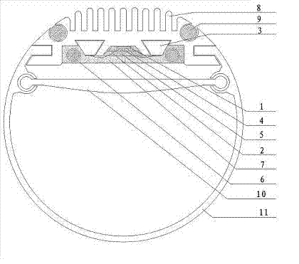
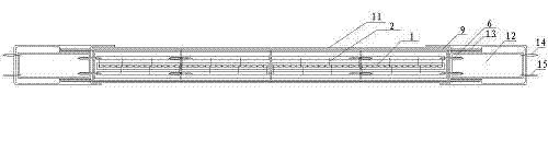
[0020] Such as figure 1 , 2 As shown, this modular high-definition LED fluorescent lamp is composed of blue LED chip 1, metal wire 2, circuit board 3, transparent silicone layer 4, phosphor layer 5, connector 6, transparent epoxy resin 7, radiator 8, connecting Part 9, secondary light distribution mirror 10, housing 11, constant current power supply module 12, constant current power supply housing 13, external power supply terminals 14, 15. Firstly, a plurality of blue LED chips 1 are implanted into the reflective cup of the heat sink 8 by using a high-precision solid crystal machine, and then through a fully automatic wire bonding machine, the metal wire 2 (gold wire is used in this embodiment) and the circuit board 3 ( In this embodiment, a PC circuit board) is electrically connected to the LED chip to complete the first process of solid crystal and wire bonding. Use a high-precision dispensing machine to put the transparent silica gel 4 into the reflective cup of the radi...


PUM


Abstract

The invention relates to a modular high-definition LED (light emitting diode) daylight lamp, which consists of a lamp carrier, a constant current power supply module, LED light sources and a PC (Polycarbonate) housing, wherein the power supply module is of an external type; the LED light sources are an integrated light source module; the light source module is composed of LED chips, metal wires, a PC circuit board, a transparent silica gel layer, a fluorescent powder layer, a connector assemblies, a transparent epoxy resin layer and a radiator; the radiator is provided with heat dissipating fins, and the bottom of the radiator is provided with a light reflection cup; the LED chips are attached at the bottom of the light reflection cup; the LED chips and the PC circuit board are electrically communicated with each other through the metal wires; the transparent silica gel layer is solidified on the chips; the fluorescent powder layer is arranged on the silica gel layer; the LED chips, the wires, the PC circuit board, the silica gel layer, the fluorescent powder layer, the connector assemblies and the radiator are solidified by the transparent epoxy resin layer to form a whole LED light source module; a plurality of LED light source modules are connected by the connector assemblies to form an integrated LED light source module, and is connected to the PC housing through connectors; and a secondary light distribution lens is arranged in front of the integrated LED light source module and at the inner side of the PC housing.

Description

technical field [0001] The invention relates to an LED fluorescent lamp, in particular to a modular high-definition LED fluorescent lamp in which a power controller, a light source and a radiator are all realized in a modular structure. Background technique [0002] Existing LED fluorescent lamps generally have a one-piece structure. The LED fluorescent lamp with an integrated structure integrates a light-emitting device, a ballast, and a radiator, and is placed in a hollow lamp tube together with a built-in power supply. Because the power supply must be placed in the lamp tube, the lamp tube cannot be made into a special shape, but can only be an ordinary semi-cylindrical shape, with some very shallow strip grooves added on the surface at most. The surface area of ​​this half cylinder is: 2πR*h / 2=πR*h. For T8 tubes, the radius is 13mm. The surface area of ​​a 1.2-meter T8 lamp tube is: π*1.3+120=490cm2. We know that the surface area of ​​an LED radiator usually requires ...

Claims


Application Information

Patent Timeline
Patent Type & Authority Patents(China)
IPC IPC(8): F21S2/00F21V29/00F21V5/00F21V23/00F21Y101/02F21V29/76
Inventor 罗业富
Owner 罗业富
Why Eureka
Try Eureka