
Single-antenna frequency-modulated continuous-wave radar radio frequency passive cancellation method

A frequency modulation continuous wave, single antenna technology, applied in the direction of radio wave measurement systems, instruments, etc., can solve the problems of large volume and weight, high difficulty in circuit design and debugging, complex system, etc., and achieve small size and good emission leakage signal cancellation effect , The effect of high transceiver isolation index

Active Publication Date: 2012-03-28
10TH RES INST OF CETC
View PDF5 Cites 30 Cited by
  • Summary
  • Abstract
  • Description
  • Claims
  • Application Information

AI Technical Summary

Problems solved by technology

[0004] The purpose of the present invention is to address the deficiencies in the above-mentioned prior art, and propose a method for passive cancellation of radio frequency in millimeter-wave single-antenna FM continuous wave radar, which achieves high transceiver isolation by transmitting leakage cancellation and feeder reflection signal cancellation, Solve the problems of complex reflection power active cancellation system, large volume and weight, and high difficulty in circuit design and debugging

Method used


Image

  • Single-antenna frequency-modulated continuous-wave radar radio frequency passive cancellation method
  • Single-antenna frequency-modulated continuous-wave radar radio frequency passive cancellation method
  • Single-antenna frequency-modulated continuous-wave radar radio frequency passive cancellation method

Examples


Embodiment Construction

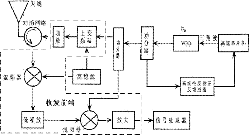
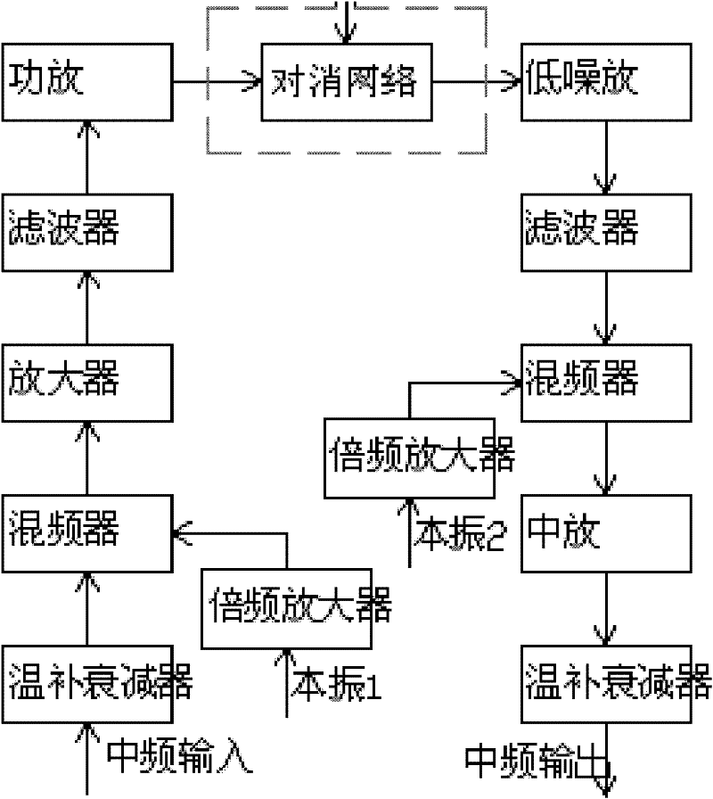
[0019] Refer to figure 1 , figure 2 . The Ka-band single-antenna FM continuous wave radar is composed of an antenna (including servo, etc.), a transceiver front-end, a video unit, and a signal processing extension. The transceiver front-end is composed of a transmitting branch and a receiving branch. The transmitting branch is composed of a power amplifier, Filter, driver amplifier, mixer, attenuator and local oscillator frequency multiplier amplifier, receiving branch is composed of low noise amplifier, filter, mixer, intermediate frequency amplifier, attenuator and local oscillator frequency multiplier amplifier, the above composition structure All are existing technologies. The passive cancellation network of the present invention is located between the radar antenna and the transceiver front end, and is used to eliminate the transmitted leakage signal and the small reflected signal caused by the discontinuity of the feeder, the antenna mismatch, and the fixed reflector ne...


PUM


Abstract

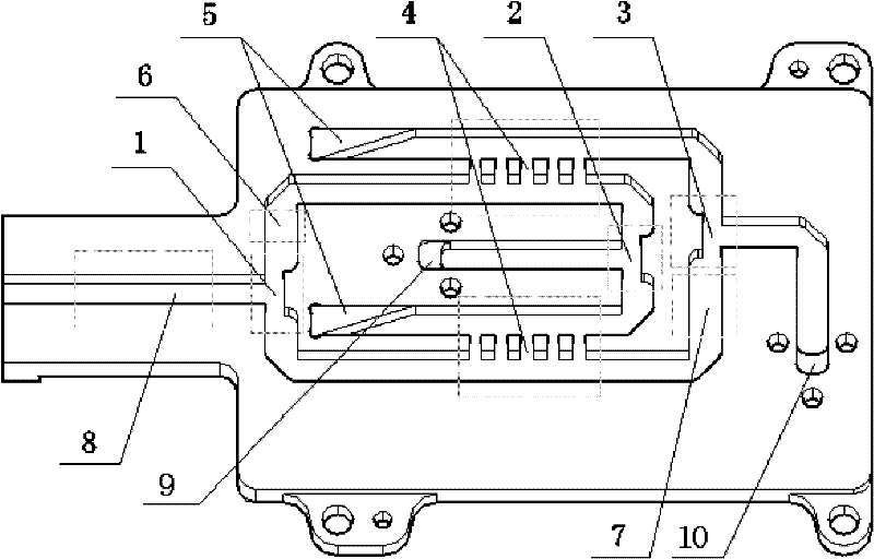
The invention provides a single-antenna frequency-modulated continuous-wave radar radio frequency passive cancellation method, and aims to provide a passive cancellation method for realizing high transceiving isolation through transmit leakage cancellation and feed line reflected signal cancellation. The method comprises the following steps of: arranging a passive cancellation network connected with a transceiving front-end circuit and a transmission line reflected signal canceller having a wave guide structure between a radar antenna and a transceiving front end, performing power division ontransmitting signals of the transceiving front end to form two paths through a transmitting T-shaped head of the passive cancellation network, allowing one path of signals to pass through a waveguidebridge and a 90-degree waveguide phase shifter and the other path of signals to pass through a 180-degree waveguide phase shifter and a waveguide bridge, synthesizing by using the T-shaped head at anoutput end, allowing the signals to pass through the transmission line reflected signal canceller, and outputting the signals to the radar antenna at the maximum power and to a receiving port at the minimum power. The passive cancellation network and the transmission line reflected signal canceller are arranged between the radar antenna and the transceiving front end, and problems that a reflected power passive cancellation system is complicated, large in volume and heavy in weight, and circuits are difficult to design and debug are solved.

Description

technical field [0001] The invention relates to a radio frequency passive cancellation method for a millimeter-wave frequency-modulated continuous-wave radar, which is applied in fields such as collision avoidance, life detection, and precise distance measurement. Background technique [0002] Ka-band single-antenna frequency-modulated continuous wave (FMCW) radar is widely used in the fields of collision avoidance, life detection, and precise ranging. It has many advantages such as no blind zone, low power consumption, low cost, and light miniaturization. In the prior art, in order to avoid the influence of transmission leakage power and mismatched reflection signals on the receiver due to feeder discontinuity, antenna mismatch, fixed reflector near the antenna, etc., the requirements for transceiver isolation are very high, which needs to reach 40~60dB. Usually, the isolation between the transceiver and the single-antenna radar can only reach 15~25dB, which cannot meet the...

Claims


Application Information

Patent Timeline
IPC IPC(8): G01S7/292G01S7/32G01S7/36
Inventor 石秀琨黄建
Owner 10TH RES INST OF CETC
Learn More