Overcurrent protection circuit
An overcurrent protection circuit and overcurrent technology, applied in the direction of overcurrent protection, current/voltage measurement, and electrical variable measurement, can solve problems such as circuit system or electronic equipment damage, and achieve low cost effects
- Summary
- Abstract
- Description
- Claims
- Application Information
AI Technical Summary
Problems solved by technology
Method used
Image


Examples
Embodiment Construction
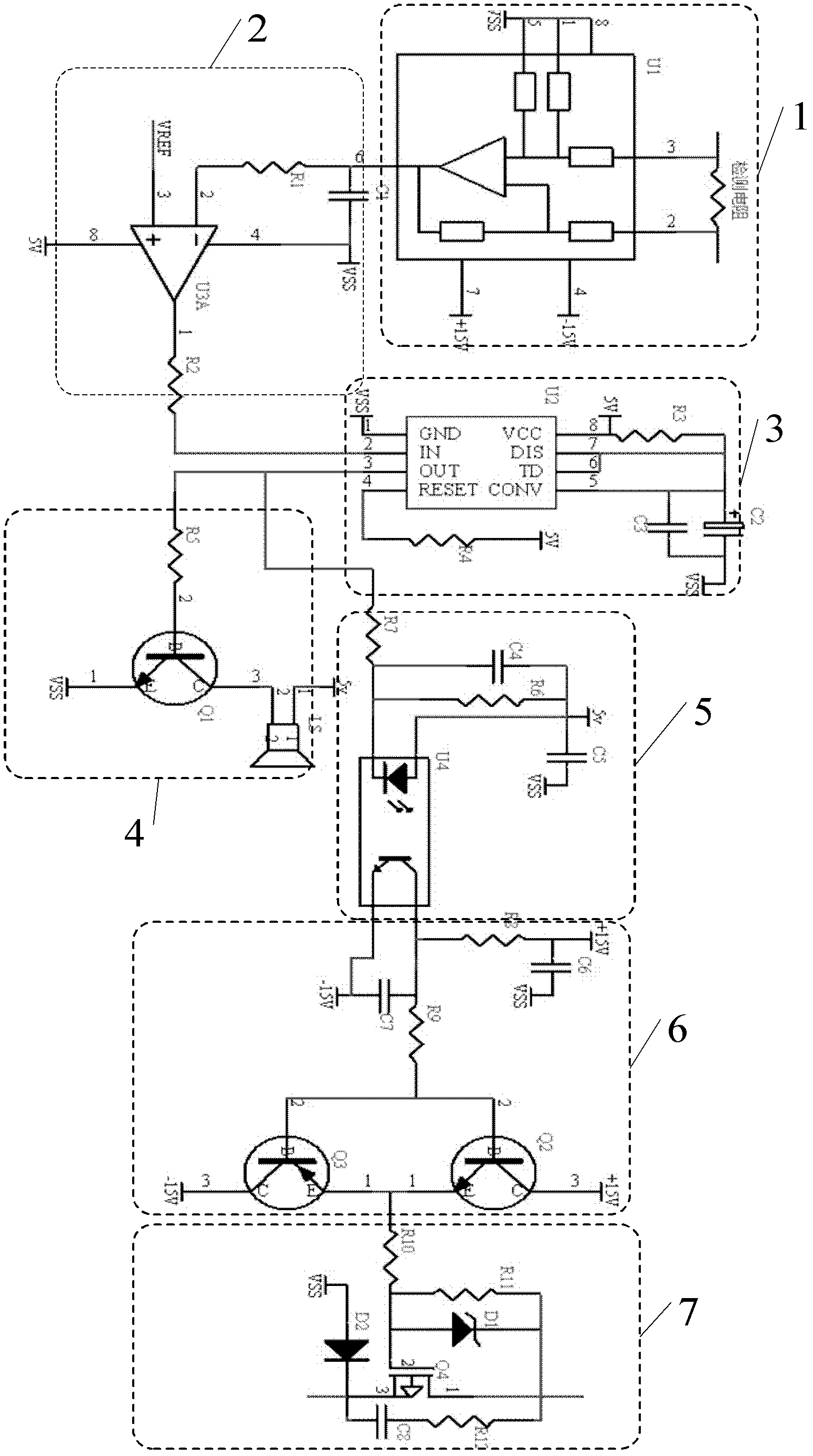
[0018] Such as figure 1 As shown, the common-mode voltage differential amplifier circuit 1 for detecting current is composed of a detection resistor and an INA117 high common-mode differential amplifier U1. The overcurrent discrimination circuit 2 is composed of No. 1 resistor R1, No. 1 capacitor C1 and comparator U3. The voltage level conversion and timing circuit 3 is composed of two No. 3 resistors R3 and No. 4 resistor R4, No. 2 capacitor C2 and No. 3 capacitor C3, and NE555 timer U2. Alarm circuit 4 is composed of No. 5 resistor R5, No. 1 transistor Q1 and buzzer LS. Photocoupler circuit 5 is composed of No. 6 resistor R6, No. 7 resistor R7, No. 4 capacitor C4, No. 5 capacitor C5, and photocoupler U4 . The totem pole circuit 6 is composed of No. 8 resistor R8, No. 9 resistor R9, No. 6 capacitor C6 and No. 7 capacitor C7, an NPN transistor Q2 and a PNP transistor Q3. The MOSFET turn-off circuit 7 is composed of No. 10 resistor R10, No. 11 resistor R11 and No. 12 resisto...
PUM
 Abstract
Description
Claims
Application Information
 - R&D
- Intellectual Property
- Life Sciences
- Materials
- Tech Scout
- Unparalleled Data Quality
- Higher Quality Content
- 60% Fewer Hallucinations
Browse by: Latest US Patents, China's latest patents, Technical Efficacy Thesaurus, Application Domain, Technology Topic, Popular Technical Reports.
© 2025 PatSnap. All rights reserved.Legal|Privacy policy|Modern Slavery Act Transparency Statement|Sitemap|About US| Contact US: help@patsnap.com