

Maximum power point tracking control method and system thereof of photovoltaic electrical energy optimization
A maximum power point and electric energy optimization technology, applied in control/regulation systems, photovoltaic power generation, photovoltaic modules, etc., can solve the problem that the incremental conductance method cannot track the maximum power point in a timely and effective manner
- Summary
- Abstract
- Description
- Claims
- Application Information
AI Technical Summary
Problems solved by technology
Method used
Image

Examples
no. 1 example
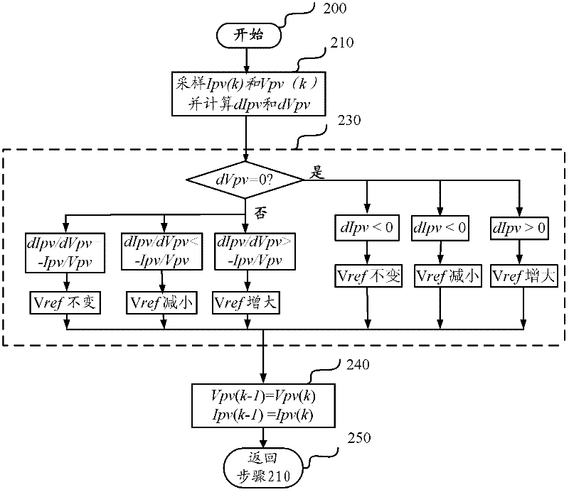
[0066] image 3 and Figure 4 They are the principle schematic diagram and flow diagram of the maximum power point tracking control method of this embodiment, respectively, and refer to figure 1 , image 3 and Figure 4 This embodiment will be described in detail.
[0067] The embodiment of the present invention is applied to the DC / DC (DC / DC) conversion stage of the photovoltaic power optimization system. Since the control of the photovoltaic power optimization system is switch control, specifically, by changing the duty cycle used to control the switch of the DC conversion stage Ratio to control the size of the reference voltage to track and control the maximum power point, the relationship between the output voltage and input voltage and the duty cycle is different due to the structure of the DC conversion stage. For example Figure 7 Schematic diagram of the structure, the relationship between voltage and duty cycle is U o / U in =1 / (1-d). The ratio of the output vo...
no. 2 example
[0125] Figure 5It is a schematic flow chart of the maximum power point tracking control method according to the second embodiment of the present invention, and this embodiment will be described in detail below with reference to the accompanying drawings.
[0126] For ease of description, the same steps as those in the foregoing embodiments will not be described in detail, but only the differences from the foregoing embodiments will be highlighted. exist Figure 5 In the same or similar steps as those in the foregoing embodiments, the same reference numerals are used.
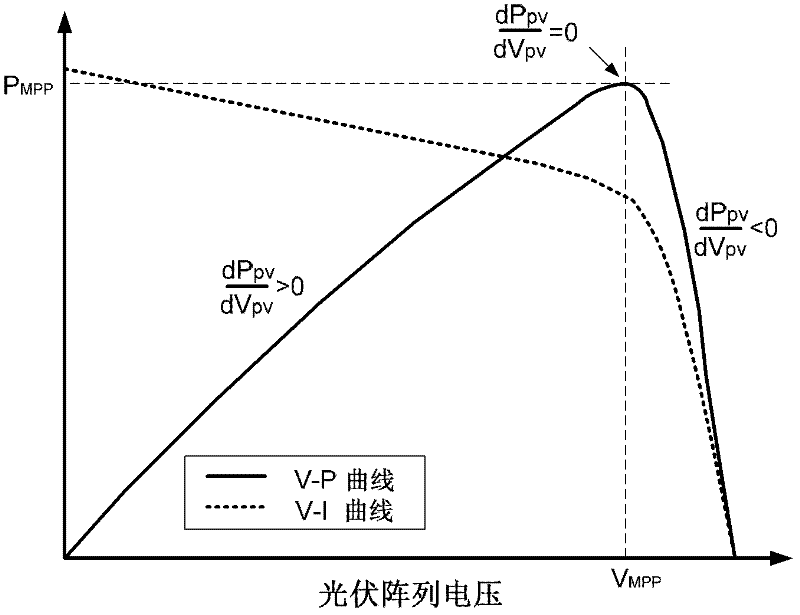
[0127] It should be noted that when the external light intensity or the environment changes, the output power of the photovoltaic module is generally proportional to the change of the output voltage, that is, at the edge of the change of the light intensity increase or decrease, dP PV / dV PV is always greater than zero, then according to formula (2), it can be obtained that when the light intensity changes s...
no. 3 example
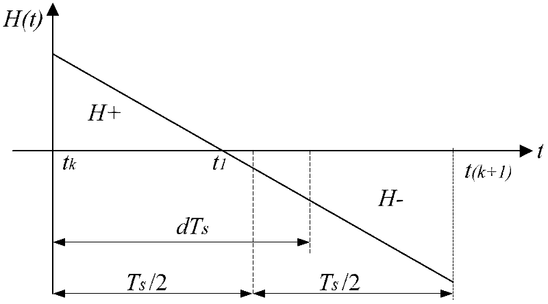
[0141] Figure 6 It is a schematic flowchart of the maximum power point tracking control method according to the third embodiment of the present invention. This embodiment is a modification of the first embodiment and the second embodiment, and the first embodiment and the second embodiment are combined. Such as Figure 6 As shown, the operation content of step 230 in the second embodiment is not executed after the operation content of step 540 in this embodiment (judging whether it is an environmental mutation) is completed, but the operation content of step 420 that is the same as that of the first embodiment is executed , by determining whether the slope H is within the preset error threshold e to control the output of the maximum power.
[0142] This embodiment first judges the change of the external environment according to the second embodiment, and then performs maximum power point tracking control according to the maximum power point tracking control method of the fir...
PUM
 Abstract
Description
Claims
Application Information