
Precoding method and matrix generating device of CoMP (coordinated multi-point) multiple-user MIMO (multiple-input multi output) system

A precoding matrix and multi-user technology, applied in diversity/multi-antenna systems, transmission systems, digital transmission systems, etc., can solve problems such as poor performance, inappropriateness, and failure to consider the impact of system performance

Inactive Publication Date: 2012-04-11
BEIJING UNIV OF POSTS & TELECOMM
View PDF4 Cites 9 Cited by
  • Summary
  • Abstract
  • Description
  • Claims
  • Application Information

AI Technical Summary

Problems solved by technology

However, BD technology must be satisfied that the number of antennas at the sending end is greater than or equal to the sum of the number of receiving antennas of all users, so BD technology is not suitable for the situation where each user at the receiving end has any receiving antenna
Moreover, BD technology only eliminates the interference between users, and does not consider the impact of noise on system performance, so when the signal-to-noise ratio decreases, its performance is relatively poor

Method used


Image

  • Precoding method and matrix generating device of CoMP (coordinated multi-point) multiple-user MIMO (multiple-input multi output) system
  • Precoding method and matrix generating device of CoMP (coordinated multi-point) multiple-user MIMO (multiple-input multi output) system
  • Precoding method and matrix generating device of CoMP (coordinated multi-point) multiple-user MIMO (multiple-input multi output) system

Examples


Embodiment Construction

[0049] The specific implementation manners of the present invention will be further described in detail below in conjunction with the accompanying drawings and embodiments. The following examples serve to illustrate the present invention, but do not limit the scope of the present invention.

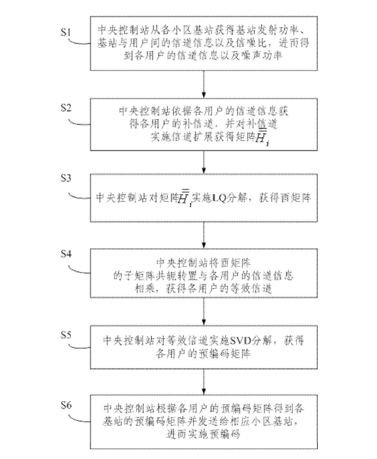
[0050] Such as figure 1 As shown, the precoding method of the present invention includes the following steps:

[0051] S1: The central control station obtains the base station transmission power P from each cell base station (eNB) n (n=1,...,T) (T is the number of cooperative cells), channel information H between base station n and user i n,i and the signal-to-noise ratio SNR n,i (i=1,...,K) (K is the number of users in the system), and then obtain the channel information H of each user i and noise power (i=1,...,K), the specific steps are:

[0052] Cell base station n (n=1,...,T) obtains channel information H through feedback or channel reciprocity n,i , SNR n,i (i=1,...,K), whe...


PUM


Abstract

The invention provides a precoding method and a matrix generating device of a CoMP (coordinated multi-point) multiple-user MIMO (multiple-input multi output) system. The method comprises the following steps that: S1, a central control station acquires base station transmitting power Pn (n=1,...,K), channel information Hn,i between a base station n and a user i and the signal-to-noise ratio SNRn,i (i=1,...K) from each cell base station n (n=1,...T) and further obtains the channel information Hi and noise power of each user, wherein T is the number of coordinated cells and K is the number of users in the system; S2, the central control station acquires a complementary channel of each user according to the channel information Hi of each user and carries out channel expansion on each complementary channel to obtain a matrix shown in the specification, wherein I is a unit matrix shown in the specification and Mk represents the number of receiving antennae of a user k; S3, the central control station carries out LQ (leadership quotient) decomposition on the matrix to obtain a unitary matrix Q1; S4, the central control station carries out conjugate transpose on the submatrix of the Qi and multiplies the submatrix subjected to conjugate transpose by Hi, thus obtaining an equivalent channel of each user; S5, the central control station carries out SVD (singular value decomposition) on each equivalent channel so as to obtain a precoding matrix Wi (i=1,...,K) of each user; and S6, the central control station obtains the precoding matrix (n=1,...T) of each base station according to the precoding matrix Wi (i=1,...,K) of each user and transmits each precoding matrix (n=1,...T) to the corresponding cell base station to further carry out precoding.

Description

technical field [0001] The invention relates to the technical field of wireless mobile communication, in particular to a precoding method and a matrix generating method of a cooperative multipoint user MIMO system. Background technique [0002] The multiple-input multiple-output (Multiple-Input Multiple-Output, MIMO) technology is a major breakthrough in the field of wireless mobile communication technology. MIMO technology refers to the use of multiple antennas for data transmission and reception. Studies have shown that using MIMO technology can increase the capacity of wireless communication systems. With the in-depth study of multi-antenna technology, MIMO technology has been extended from point-to-point single-user MIMO technology to point-to-multipoint multi-user MIMO system (Multiple User MIMO, MU-MIMO). In MU-MIMO technology, the multi-antenna diversity gain can effectively reduce the system bit error rate, and the multi-antenna multiplexing gain can expand the cap...

Claims


Application Information

Patent Timeline
IPC IPC(8): H04L1/00H04B7/06
CPCH04B7/06H04B7/024H04L5/0035H04L1/00H04B7/0456
Inventor 李立华张平王化磊王骥
Owner BEIJING UNIV OF POSTS & TELECOMM
Learn More