
Recovery device for sensible heat of powdery solid

A sensible heat recovery, powder-like technology, applied in the direction of waste heat treatment, indirect heat exchangers, heat exchanger types, etc., can solve the problem of inconvenient popularization and use of powder-like solid waste heat utilization devices, failure to meet industrial and environmental protection needs, boiler systems can not Normal work and other problems, to achieve the effect of uniform and stable heat transfer, reasonable structure, and increase the amount of waste heat recovery

Active Publication Date: 2013-06-19
大连九五高科新能源发展有限公司
View PDF4 Cites 0 Cited by
  • Summary
  • Abstract
  • Description
  • Claims
  • Application Information

AI Technical Summary

Problems solved by technology

There are certain deficiencies in this method: first, the cross-section of the material inlet is smaller than the cross-section of the heat exchange fluid, so that when the material enters, it is easy to be unevenly distributed, resulting in that the heating surface cannot be fully utilized; second, due to the small particle size of the material, the circulation channel There is no device to promote the flow of materials, which can easily cause the materials to block in the shaft, and the boiler system cannot work normally; third, the materials are in direct contact with the heating surface. When the heating surface leaks, the entire system needs to be stopped for maintenance
Therefore, the powdery solid waste heat utilization device used in this technology is inconvenient to be popularized and used, and cannot meet the needs of industry and environmental protection

Method used


Image

  • Recovery device for sensible heat of powdery solid
  • Recovery device for sensible heat of powdery solid
  • Recovery device for sensible heat of powdery solid

Examples


specific Embodiment approach

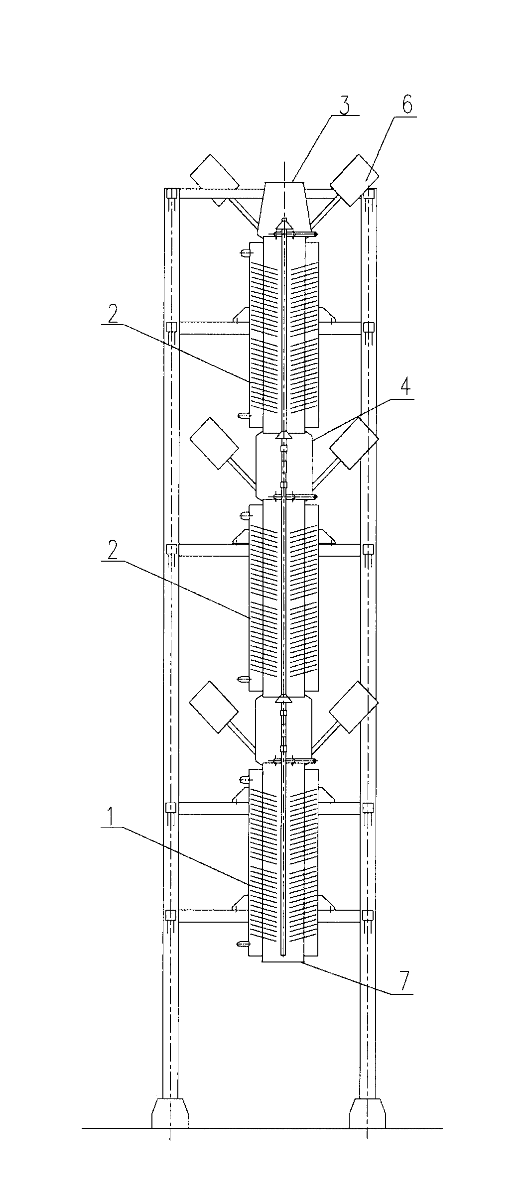
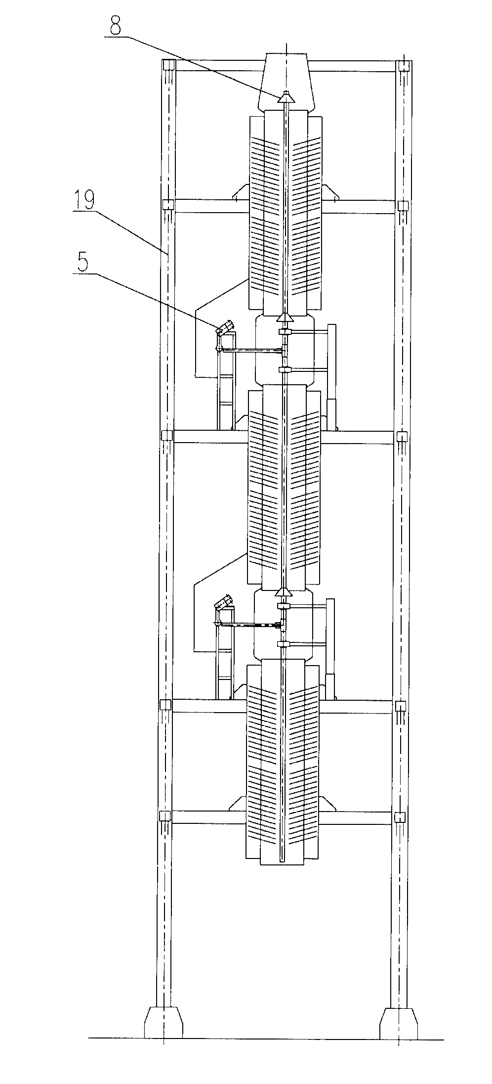
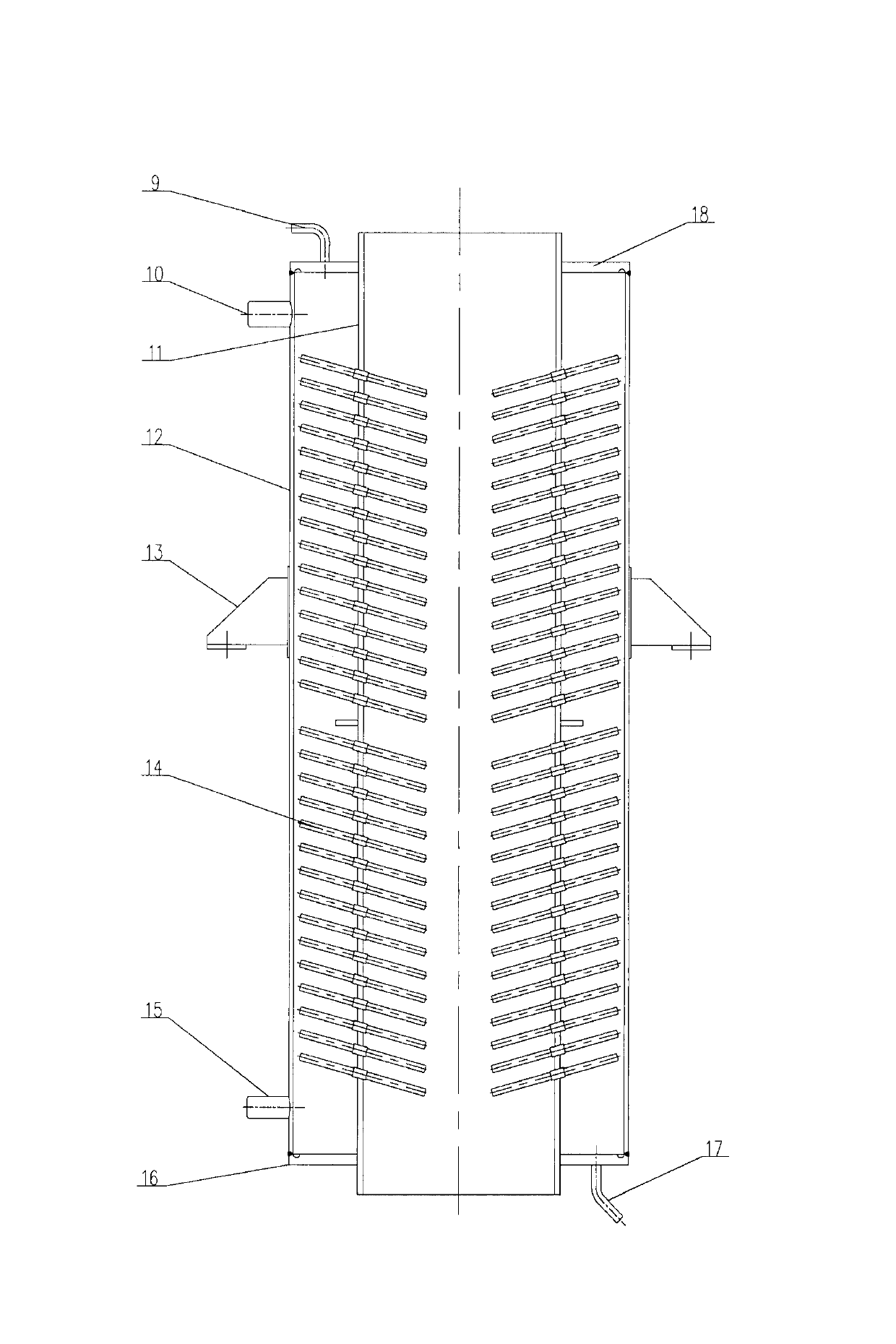
[0022] detailed description The invention mainly includes a coal economizer, an evaporator, a pipeline, a material inlet and a material outlet. The upper part of the economizer is vertically connected to the evaporator through the pipeline in turn. The top port of the top evaporator is the material inlet, and the bottom port of the bottom economizer is the material Outlet; there is a support frame around the economizer and evaporator, and each layer of economizer and evaporator is welded on the support frame; the economizer and evaporator have the same structure, and are composed of an inner cylinder and an outer cylinder. There is a coaxial inner cylinder in the outer cylinder, and the inner and outer cylinders are welded and closed by the upper head and the lower head to form an annular cylinder; one end of the heat pipe is inserted into the interlayer of the inner and outer cylinders, and the other end is in the inner cylinder; in the economizer The lower end of the out...

Embodiment 1

[0026] Two evaporators and one economizer are selected. The economizer is located at the bottom, and then the evaporators are connected layer by layer upward to form a vertical connection structure. There are supporting frames outside the evaporator and the economizer. The frame is composed of four vertical support legs and multiple beams to form a cubic frame structure. The support frame surrounds the evaporator and economizer, and is welded together with the ear brackets of the evaporator and economizer through horizontal metal rods. The bracket consists of two brackets, which are symmetrically installed on the outer walls of the evaporator and the economizer. The evaporator and the economizer are composed of inner and outer cylinders, and the inner and outer cylinders all adopt a cylindrical structure, and the upper and lower seals form a ring structure, and the upper and lower adjacent evaporators (or evaporators and economizers) are connected by pipelines. The pipe adopts...

Embodiment 2

[0028] Three evaporators and one economizer are selected, the economizer is at the bottom, and then the evaporators are connected and installed layer by layer upwards, forming a vertical connection structure as a whole, and there are supporting frames outside the evaporator and the economizer. The support frame consists of four vertical support legs and a plurality of beams to form a cubic frame structure. The support frame surrounds the evaporator and the economizer, and is welded together with the ear brackets of the evaporator and the economizer through horizontal metal rods , The ear bracket consists of three brackets that are triangularly symmetrically distributed on the outside of the evaporator and economizer. A coaxial rapping rod is installed in the inner cylinder. In order to ensure that the solid powder can evenly fall from the inner cylinder into the ash hopper, a distributor is installed on the rapping rod, and a rapping hammer is arranged at the pipeline between t...


PUM


Abstract

The invention discloses a recovery device for the sensible heat of powdery solid. The device comprises a coal economizer, evaporators, pipelines, a material inlet and a material outlet. The evaporators are vertically connected in turn above the coal economizer through the pipelines. A top opening of the top-layer evaporator is the material inlet. A bottom opening of the bottom-layer coal economizer is the material outlet. A support frame is covered around the outside of the coal economizer and the evaporators. The coal economizer and evaporator of each layer are welded to the support frame. The coal economizer and the evaporator have the same structure, and consist of an inner tube and an outer tube respectively. The coaxial inner tube is arranged in the outer tube. The inner and outer tubes are welded and formed through an upper end enclosure and a lower end enclosure to form an annular tube. One end of a heat pipe is inserted into an interlayer between the inner and outer tubes, andthe other end of the heat pipe is positioned in the inner tube. The lower ends of the outer tubes of the coal economizer and the evaporator are communicated with a water inlet pipe, and the upper ends of the outer tubes of the coal economizer and the evaporator are communicated with a water outlet pipe. The device has the advantages of rational structure, convenience of use, heat exchange uniformity and stability, safety, reliability and the like.

Description

technical field [0001] The invention relates to a waste heat recovery device, in particular to a device for recovering powdery solids in the smelting industry. Background technique [0002] It is known that in the smelting industry, a large amount of waste heat resources will be generated, such as the waste heat resources generated in the magnesia and alumina production industries. This kind of waste heat is mainly composed of two parts: 1. Calcined waste gas from kilns; 2. Sensible heat from the powdery solid product produced after calcination. At present, the use of waste heat is only to introduce the calcination waste gas into the waste heat boiler to generate steam, and then use the steam to do work; but there is no better way to use the sensible heat of the calcined product, usually by air cooling. The heat of the cooling gas is reused, so that the cooling efficiency is low and a large amount of high-temperature resources are wasted. [0003] At present, in the ex...

Claims


Application Information

Patent Timeline
Patent Type & Authority Patents(China)
IPC IPC(8): F28D17/02F27D17/00
CPCY02P10/25
Inventor 唐金泉金万金孙明朗滕小平尤长升
Owner 大连九五高科新能源发展有限公司
Learn More