Ultra-wide bandwidth radar type non-contact life parameter real-time monitoring system
A technology for real-time monitoring systems and life parameters, applied in radio wave measurement systems, measurement devices, and radio wave reflection/re-radiation, etc., can solve problems such as non-contact monitoring and limited penetration capability.
- Summary
- Abstract
- Description
- Claims
- Application Information
AI Technical Summary
Problems solved by technology
Method used
Image
Examples
Embodiment 1
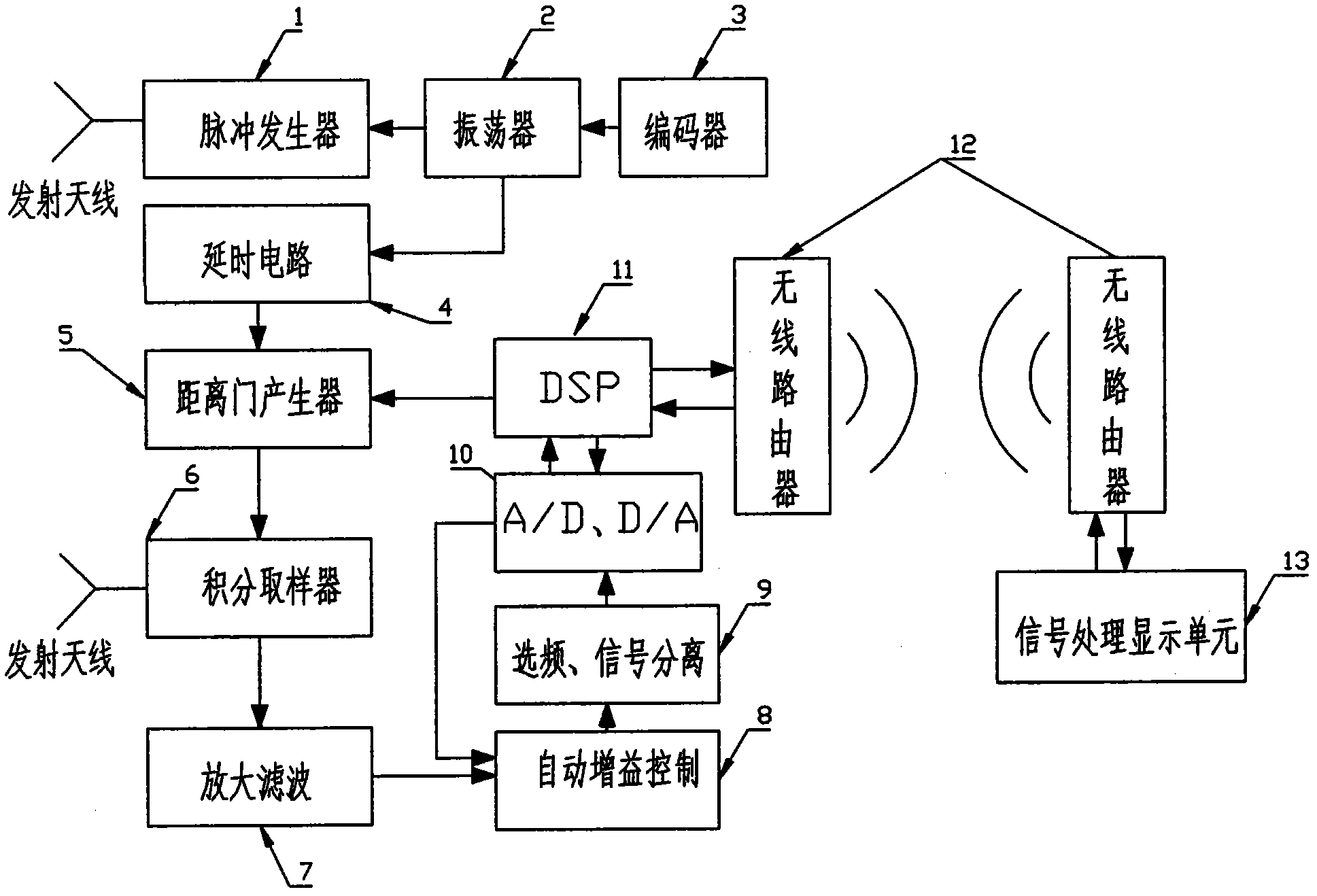
[0035] The principle block diagram of the ultra-wide spectrum radar real-time monitoring system for vital parameters is as follows: figure 1 As shown, it includes a UWB radar front end, a wireless network, and a signal processing display unit 13 , and the UWB radar front end and the signal processing display unit 13 are connected through a wireless router 12 . The UWB radar front end includes a transmitting antenna, a receiving antenna, an encoder 3, an oscillator 2, a pulse generator 1, a delay circuit 4, a range gate generator 5, an integral sampler 6, an amplification filter circuit 7, an automatic gain Control circuit 8, frequency selection, signal separation circuit 9 and DSP (digital signal processing, Digital Signal Processing) 11; Described encoder 3 controls described oscillator 2 to generate pulse signal, and this pulse signal triggers pulse generator 1 to generate electromagnetic narrow pulse, and radiate out by the transmitting antenna; the reflected signal is sent...
Embodiment 2
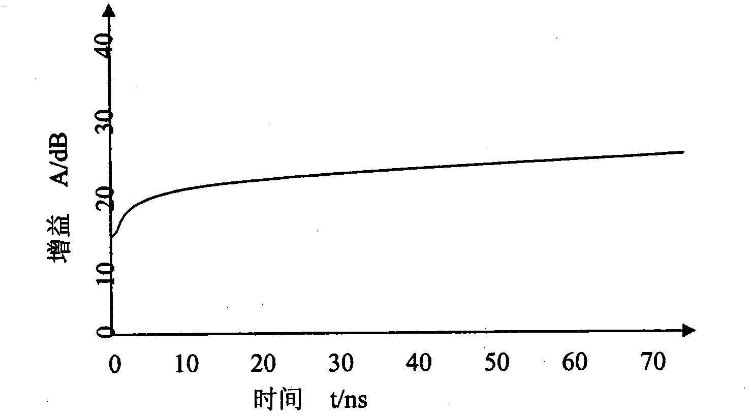
[0043] Automatic gain control circuit 8: Due to the influence of various factors such as the reflection of electromagnetic waves on the surface of the medium and the propagation attenuation in the medium, the amplitude of the target signal received by the UWB radar is generally very weak, and with the increase of the distance from the radar Decays quickly. In order to compensate the attenuation of the signal, the system adopts the automatic gain control circuit 8 before A / D. The design of the automatic gain control circuit 8 adopts 8-stage secondary variable gain setting, and through two automatic variable gain settings, the target signal received by the radar is compensated and amplified, which improves the signal-to-noise ratio very well.
[0044] The specific method is: first, when the gain is 1, collect the echo signal for a certain period of time, obtain the background parameters, divide the monitoring distance into 8 sections on average, and generate 8 gain values acco...
Embodiment 3
[0046] Frequency selection and signal separation circuit 9: the automatic gain control circuit 8 enables the signal to be further nonlinearly amplified, while limiting the amplification of strong signals; then the signal is sent to the frequency selection and signal separation circuit 9 for frequency selection, and the frequency selection and signal separation circuit 9 Including five band-pass hardware filters, respectively: 0.05~3.3Hz, 0.05~10Hz, 0.05~20Hz, 0.05~30Hz, 0.05~40Hz. After filtering out interference and noise, the signal-to-noise ratio of the signal is greatly improved, and a purer mixed signal (that is, the signal after frequency selection) is obtained. The signal after frequency selection enters the separation circuit in the frequency selection and signal separation circuit 9, and separates the mixed signal to form two signals of breathing and body movement. The two signals are sent to the A / D acquisition module for sampling through their respective output stage...
PUM
 Abstract
Description
Claims
Application Information
 - R&D
- Intellectual Property
- Life Sciences
- Materials
- Tech Scout
- Unparalleled Data Quality
- Higher Quality Content
- 60% Fewer Hallucinations
Browse by: Latest US Patents, China's latest patents, Technical Efficacy Thesaurus, Application Domain, Technology Topic, Popular Technical Reports.
© 2025 PatSnap. All rights reserved.Legal|Privacy policy|Modern Slavery Act Transparency Statement|Sitemap|About US| Contact US: help@patsnap.com


