Film combining machine

A film laminating machine and film machine technology, applied in the direction of external support, transport packaging, multiple packages, etc., can solve the problems of high preparation and operation costs, easy failure, and low working efficiency of the glue pressing device, so as to save production Production cost, stable and noiseless operation, and the effect of improving product pass rate

Active Publication Date: 2012-04-25
HUNAN KENON AUTOMATIC EQUIP
View PDF8 Cites 7 Cited by
  • Summary
  • Abstract
  • Description
  • Claims
  • Application Information

AI Technical Summary

Problems solved by technology

[0003] The existing film laminating machine has disadvantages such as complex operation, high preparation and operation costs, and its structure and layout need to be further optimized, which is specifically reflected in the following aspects
[0004] 1. The structure of the extruding device in the existing film laminating machine is complex and the production cost is high: first, the glue outlet of the extruding device (screw extruder) is connected to the extruding device through a thermal insulation hose. The length is about 1200mm, and it has special production requirements, and the production cost is relatively high; while the glue dispensing device is fixed on an up and down movement mechanism. It is convenient for the extrusion nozzle of the glue discharge device to be inserted into the film for glue application, and a set of film hooking mechanism is also set to hook the film rolled on the material guide tube; when not applying glue, the up and down movement mechanism moves upward to squeeze the glue The nozzle is far away from the material guide pipe. Since the extrusion action cannot be stopped when the glue is applied or not applied, the speed can only be slowed down, otherwise the extrusion nozzle will be blocked, which requires a glue connection mechanism. The existing The glue splicing mechanism is driven by a set of rotating mechanism to turn over for glue splicing. Its structure is relatively complicated, which increases the production cost and the difficulty of debugging.
[0005] 2. The material in the existing mold clamping machine is driven by two synchronous belt drive mechanisms, and the two synchronous belt drive mechanisms are only driven by one motor. Tooth skipping, poor equipment stability
[0006] 3. The working efficiency of the gluing device in the existing film laminator is low: the gluing wheel used for gluing in the existing laminator is cylindrical, and the upper part of the guide tube that fits the gluing wheel is flattened to make it It has a small surface, and then presses the glue through the flat contact pressing wheel. However, there has always been a big problem for small-diameter charge machines, that is, how to increase production capacity, and the bottleneck of increasing production capacity is the inner diameter of the material guide tube. Size and length, because the outer diameter of the guide tube and the collar shaper are limited by the size of the drug roll itself, if the outer diameter cannot be increased, it is possible to increase the production capacity only by increasing the inner diameter, but as mentioned above, the upper part of the guide tube should be flattened The glue pressing method makes the tube wall of the guide tube must be made thick, so that the upper part of the guide tube will not be cut through when the upper part of the guide tube is cut, and the result of thickening the tube wall under the premise of the same outer diameter is to make the The inner diameter of the guide tube is smaller, which greatly affects the passing capacity of the filling material, and also greatly reduces the production capacity and production efficiency of the laminating machine.
[0007] 4. The forming device of the existing film laminating machine includes a collar former and a material guide tube, but the collar former and the material guide tube are respectively fixed on the vertical plate, and installation and replacement need to be performed one by one, which is inconvenient to install and replace ,low efficiency
[0008] 5. The speed synchronization device between the film conveying device and the rotary punching and cutting device of the existing film laminating machine drives the eccentric wheel fixed on the rotating shaft to rotate through the swing arm rotating mechanism, and then senses the distance between the eccentric wheel and the eccentric wheel through the sensor Change to feedback speed, every time the swing arm rotation mechanism rotates a certain angle, the distance between the eccentric wheel and the sensor will change to a certain extent, the conversion device of this kind of eccentric wheel has the disadvantage of slow response speed, and its synchronization effect will not good
[0009] 6. In addition, in the existing production line for film laminating and filling, the film splicing machine, automatic deviation correction device, and laminating machine are basically arranged along a straight line. The equipment space takes up a lot, and the distance between the laminating machine and the laminating machine is large It is inconvenient for operators to control and operate two devices at the same time

Method used


Image

  • Film combining machine
  • Film combining machine
  • Film combining machine

Examples


Embodiment Construction

[0039] The present invention will be further described in detail below in conjunction with the accompanying drawings and specific embodiments.

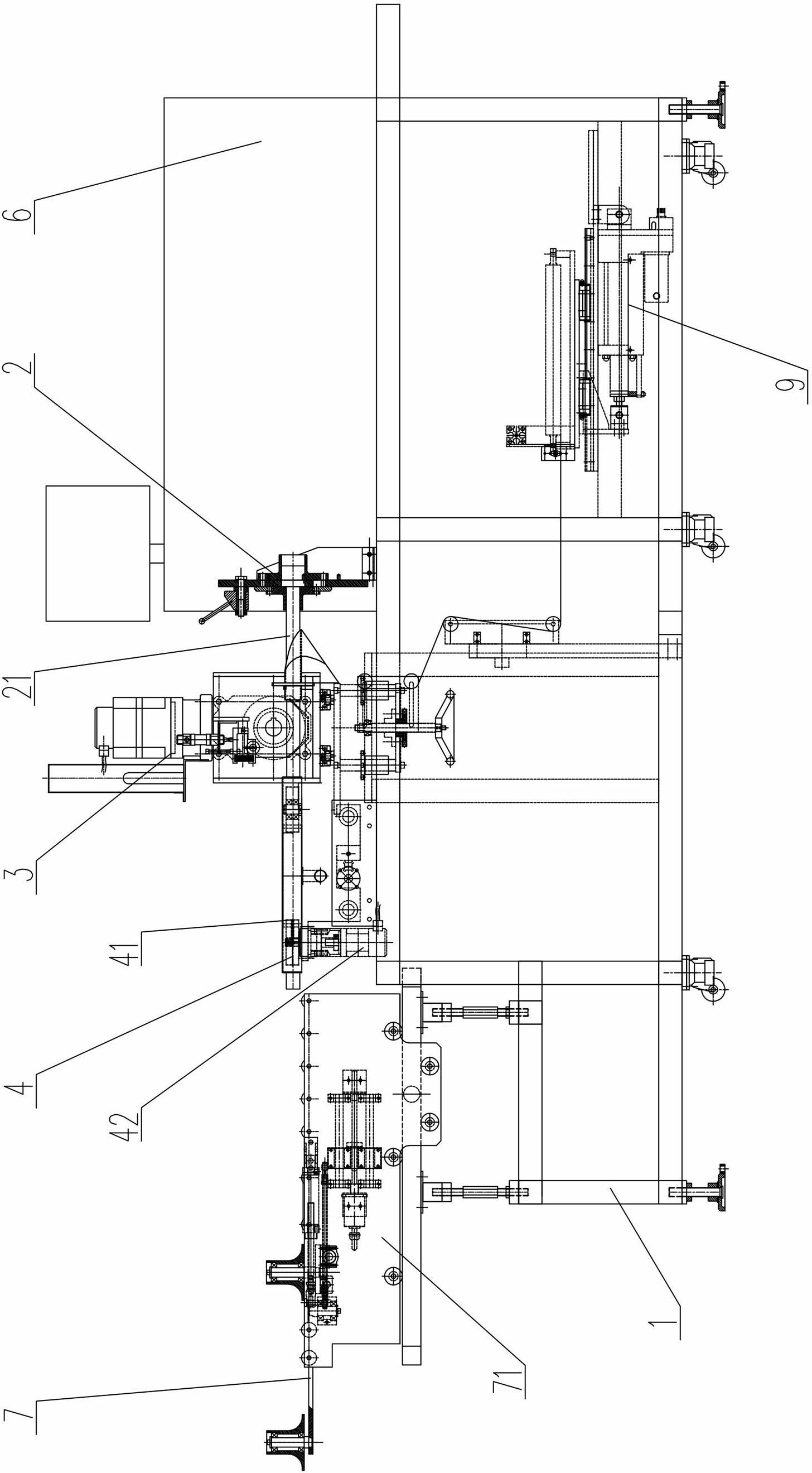
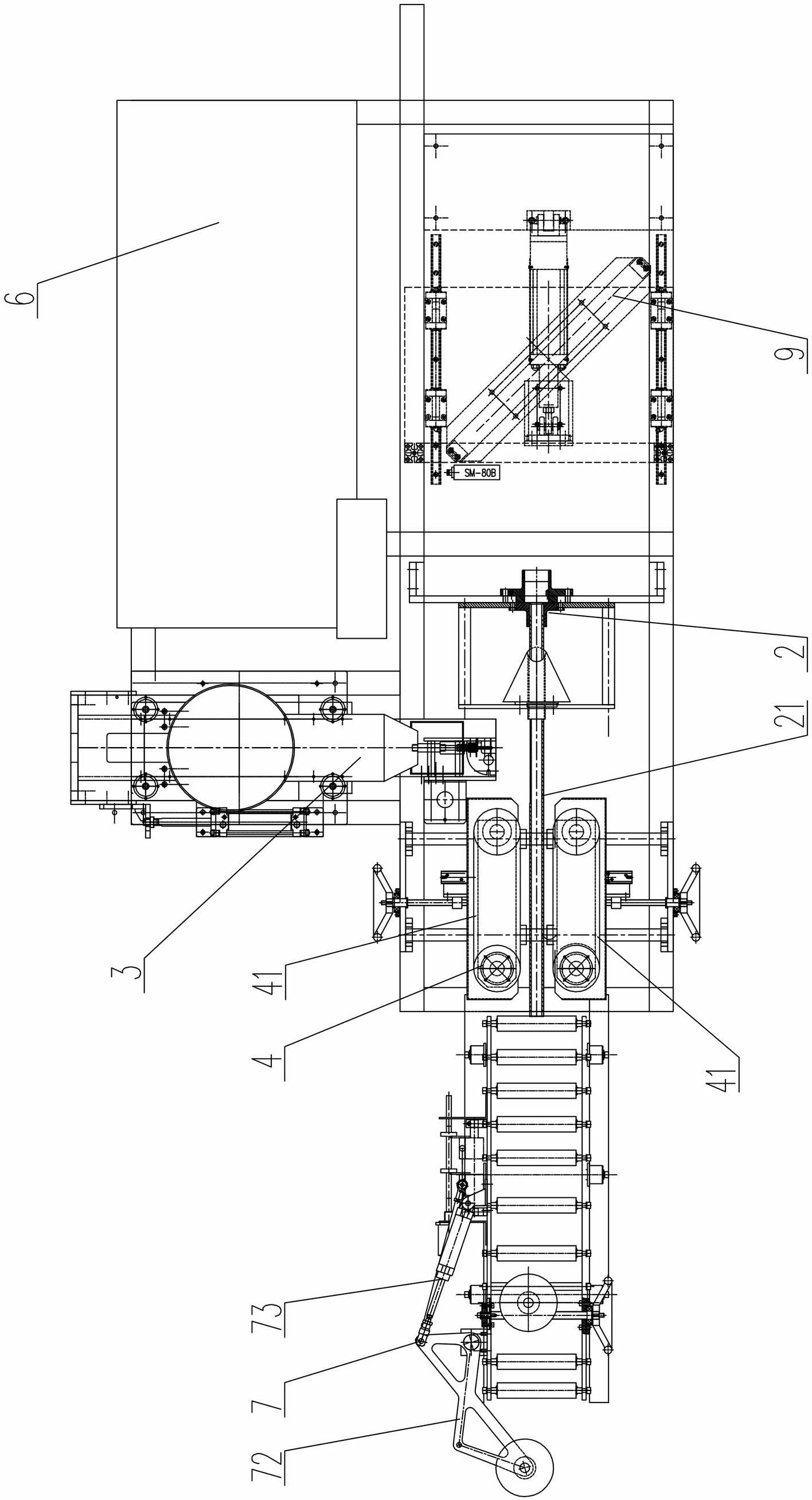
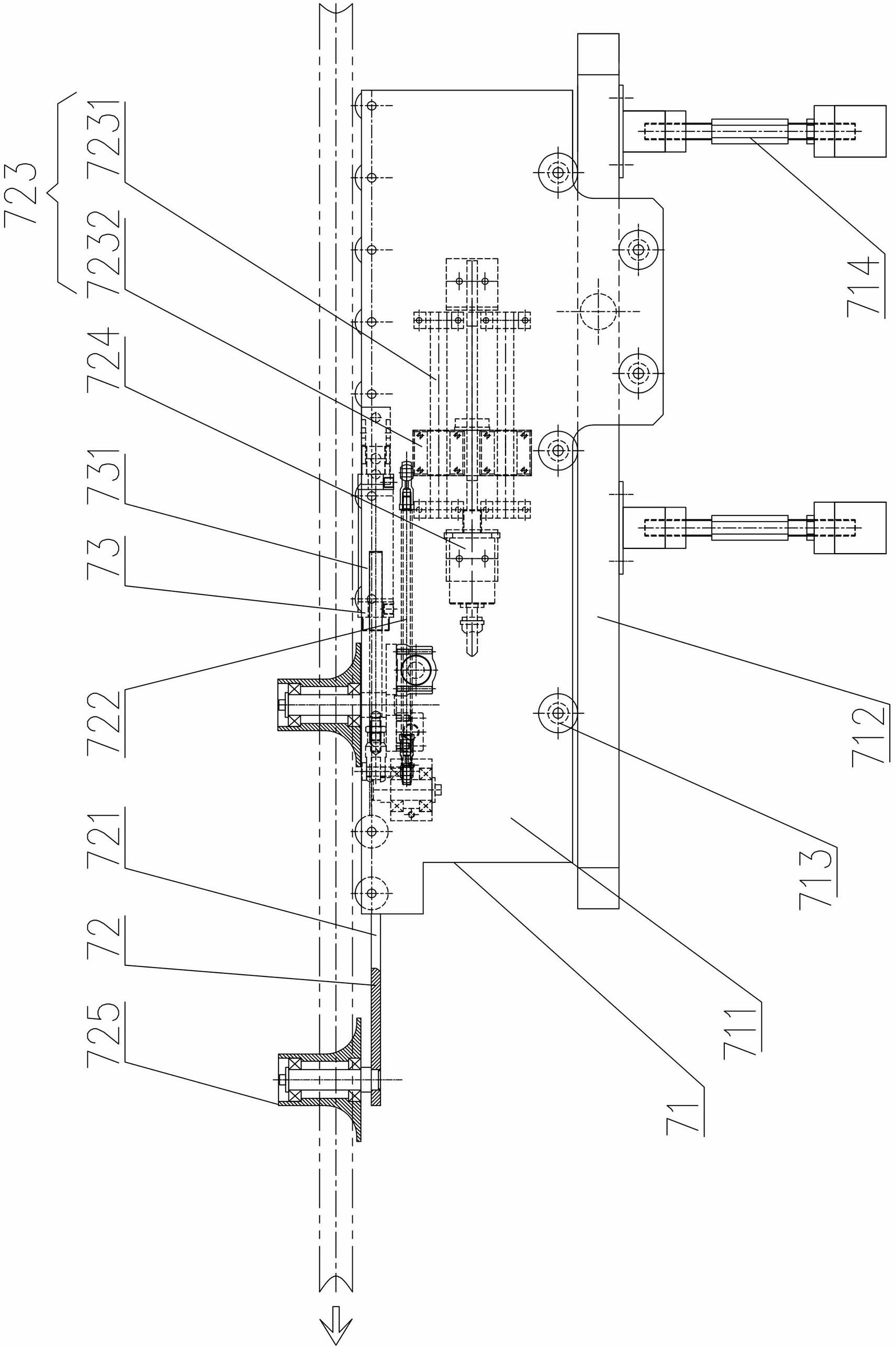
[0040] Figure 1 to Figure 11 Shown is an embodiment of the film laminating machine of the present invention, including forming device 2, gluing device 3, material driving device 4, electric control device 6 and speed synchronization device 7 arranged on frame 1, gluing device 3 It includes a glue-discharging mechanism 35 and a glue-squeezing mechanism 36 that supplies glue to the glue-discharging mechanism 35. The glue-discharging mechanism 35 is directly connected to the glue outlet of the glue-discharging mechanism 36. The glue-discharging mechanism 36 is installed on a horizontal driving mechanism 31 so that The glue-discharging mechanism 35 only moves along the horizontal direction to apply glue, and the glue-extruding mechanism 36 is directly set at the glue outlet of the glue-discharging mechanism 35, and is driven by the horiz...


PUM

PropertyMeasurementUnit
lengthaaaaaaaaaa

Abstract

The invention discloses a film combining machine, which comprises a forming device, a glue coating device, a material driving device, an electric control device and a speed synchronization device, wherein the forming device, the glue coating device, the material driving device, the electric control device and the speed synchronization device are arranged on a machine frame, the glue coating device comprises a glue outlet mechanism and a glue extruding mechanism for supplying glue to the glue outlet mechanism, the glue outlet mechanism is directly connected with a glue outlet of the glue extruding mechanism, and the glue extruding mechanism is arranged on a horizontal driving mechanism so that the glue outlet mechanism only moves in the horizontal direction for coating the glue. The film combining machine has the advantages that the structure is simple, the cost is low, the reliability and the harmony are high, the installation and the debugging are convenient, the production capacity and the production efficiency are greatly improved, and the like.

Description

technical field [0001] The invention mainly relates to the field of packaging machinery, in particular to a laminating machine for plastic film packaging. Background technique [0002] Plastic film packaging products such as ham sausage, quick-frozen food and other liquid, pasty items, and chemicals with high and medium viscosity are usually filled and produced on a laminating machine. The laminating machine is composed of multiple joint-action equipment. At the same time, the plastic film is crimped through the collar former. After crimping, it is glued and bonded firmly by the gluing device, and then it is filled. After filling, it is transported to the rotary punching and cutting device by the film conveying device for punching and cutting, so that Complete the entire production from plastic film to finished product. [0003] The existing film laminating machine has disadvantages such as complex operation, high preparation and operation costs, and its structure and layou...

Claims


Application Information

Patent Timeline
Patent Type & Authority Applications(China)
IPC IPC(8): B65B51/02B65B41/02B65B9/00
Inventor 李智峰敬亚
Owner HUNAN KENON AUTOMATIC EQUIP
Why Eureka
Try Eureka