Arrangement method for anode unit for electrolysis

A layout method and anode technology, applied in electrolysis components, electrodes, electrolysis process, etc., can solve the problems of unsatisfactory, small feed rate of milling ear, increase of production cost, etc., so as to reduce production cost, prolong the life of milling cutter, reduce Effect of small milling forces

Active Publication Date: 2012-04-25
JIANGXI NERIN EQUIP
View PDF0 Cites 6 Cited by
  • Summary
  • Abstract
  • Description
  • Claims
  • Application Information

AI Technical Summary

Problems solved by technology

[0004] The disadvantages of the above two arrangement methods are: the receiving of anode plates, slicing, vertical ear straightening, weighing, plate surface flattening and thickness measurement, side milling ears, bottom milling ears, equidistant arrangement and other functional equipment are arranged in series, The transportation track of the anode plate is also connected in series step by step. Since the milling lug area of ​​the side milling lug to the anode is large, the feed rate of the milling lug needs to be small. The ear function takes a lot of time, resulting in a significant drop in the production capacity of the anode unit. For example, the production capacity of the latest technology anode unit is 450 pieces / hour (without side milling ears). Under the condition that 20% of the anode plates need side milling ears, The production capacity of the unit is reduced to 370 pieces / hour, so the unit cannot meet the requirements of the electrolysis operation rate, and the production time of the unit is extended, the labor time of the workers increases, and the production cost increases

Method used


Image

  • Arrangement method for anode unit for electrolysis
  • Arrangement method for anode unit for electrolysis

Examples


Embodiment Construction

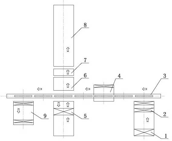
[0011] A method for arranging an anode unit for electrolysis, the equipment of the method includes a plate receiving device 1 capable of receiving anodes, a plate receiving chain transport machine and slices, vertical straightening ears, a weighing mechanism 2, a traverse device 3, and a plate surface Shaping press and thickness measuring device 4, side milling ear device 5, bottom milling ear device 6, inclined lifting device 7, plate chain conveyor and plate rack 8 and waste plate removal equipment 9; the traverse device 3 The side milling lug device 5 is arranged on one side of the head, and the bottom milling lug device 6 is arranged on the other side; in this way, the anode plate without the side milling lug is directly sent to the Enter the bottom milling ear position for bottom milling ear; the anode plate that needs side milling ear is sent to the side milling ear position for side milling ear, after the side milling ear is completed, it is sent to the bottom milling ea...


PUM


Abstract

The present invention discloses an arrangement method for an anode unit for electrolysis. Equipment of the method comprises: an acceptance plate apparatus capable of reception of the anode, an acceptance plate chain conveyor and separation piece, a vertical correction ear, a weighing mechanism, a traversing chain conveyor, a plate surface shaping pressure machine and thickness measuring device, a side lug milling device, a bottom lug milling device, an oblique lifting device, and a plate arrangement chain conveyor and plate arrangement frame. The arrangement method of the present invention has the following advantages that: the side lug milling function forms an open circuit or a parallel connection in the unit system, such that the side lug milling device can work separately, the work of the anode unit system is not affected, the production capacity of the anode unit is not reduced substantially in spite of increase of the anode lug thickness, the reduction of the production capacity is proportional to the number of the anode requiring lug milling, the unit can meet the requirements of the electrolysis operation rate; meanwhile the speed of the side lug milling can be properly reduced, such that the milling force can be reduced so as to prolong the service life of the mill, and reduce the production cost.

Description

technical field [0001] The invention relates to a copper electrolysis device, in particular to a method for arranging a side milling ear device of an electrolysis anode processing unit. Background technique [0002] Copper is an important resource of the national economy, and the refining of high-purity cathode copper is produced by electrolysis. Since the anode for electrolysis is produced by casting, the deformation of the anode plate is relatively large, and the dimensional error is also large. In order to improve the drape of the anode plate during production, reduce short circuits, reduce contact resistance, and improve electrical efficiency, on the one hand, it is necessary to use the anode plate during casting. To improve the quality of the cast anode plate, on the other hand, it is necessary to use the anode unit to process the anode plate. At present, the most advanced anode unit has the functions of anode plate receiving, slicing, vertical ear straightening, weigh...

Claims


Application Information

Patent Timeline
Patent Type & Authority Applications(China)
IPC IPC(8): C25C1/12
CPCC25C7/02C25C1/12B23C3/00B23P23/06Y10T29/49204Y10T29/49108B21D1/00B23C2220/28B23Q7/14B23Q2717/006
Inventor 邓爱民余智艳邵晓光蒲彦雄黄程凯刘小臣任智顺陆为民于军
Owner JIANGXI NERIN EQUIP
Why Eureka
Try Eureka