Field installation method for vertical-shaft wind-driven generator

A technology for wind turbines and on-site installation, which is applied to wind turbine components, wind engines, and wind engines at right angles to the wind direction, etc. It can solve problems such as troublesome installation and debugging, long installation period, and high installation cost Simplicity, reduced manufacturing cost and transportation cost, and reduced difficulty in maintenance

Active Publication Date: 2012-04-25
GUANGZHOU YATU NEW ENERGY TECH
View PDF6 Cites 12 Cited by
  • Summary
  • Abstract
  • Description
  • Claims
  • Application Information

AI Technical Summary

Problems solved by technology

The generator of this structure is an outer rotor generator, and the inner stator surrounds the central tower. In order to make the structure firm, the diameter of the central tower is generally made relatively large. Therefore, the diameter of the generator also needs to be made very large accordingly. The exciter should also be relatively large; for such a large equipment, installation and debugging are very troublesome, and the installation period is long and the installation cost is huge

Method used


Image

  • Field installation method for vertical-shaft wind-driven generator
  • Field installation method for vertical-shaft wind-driven generator
  • Field installation method for vertical-shaft wind-driven generator

Examples


Embodiment 1

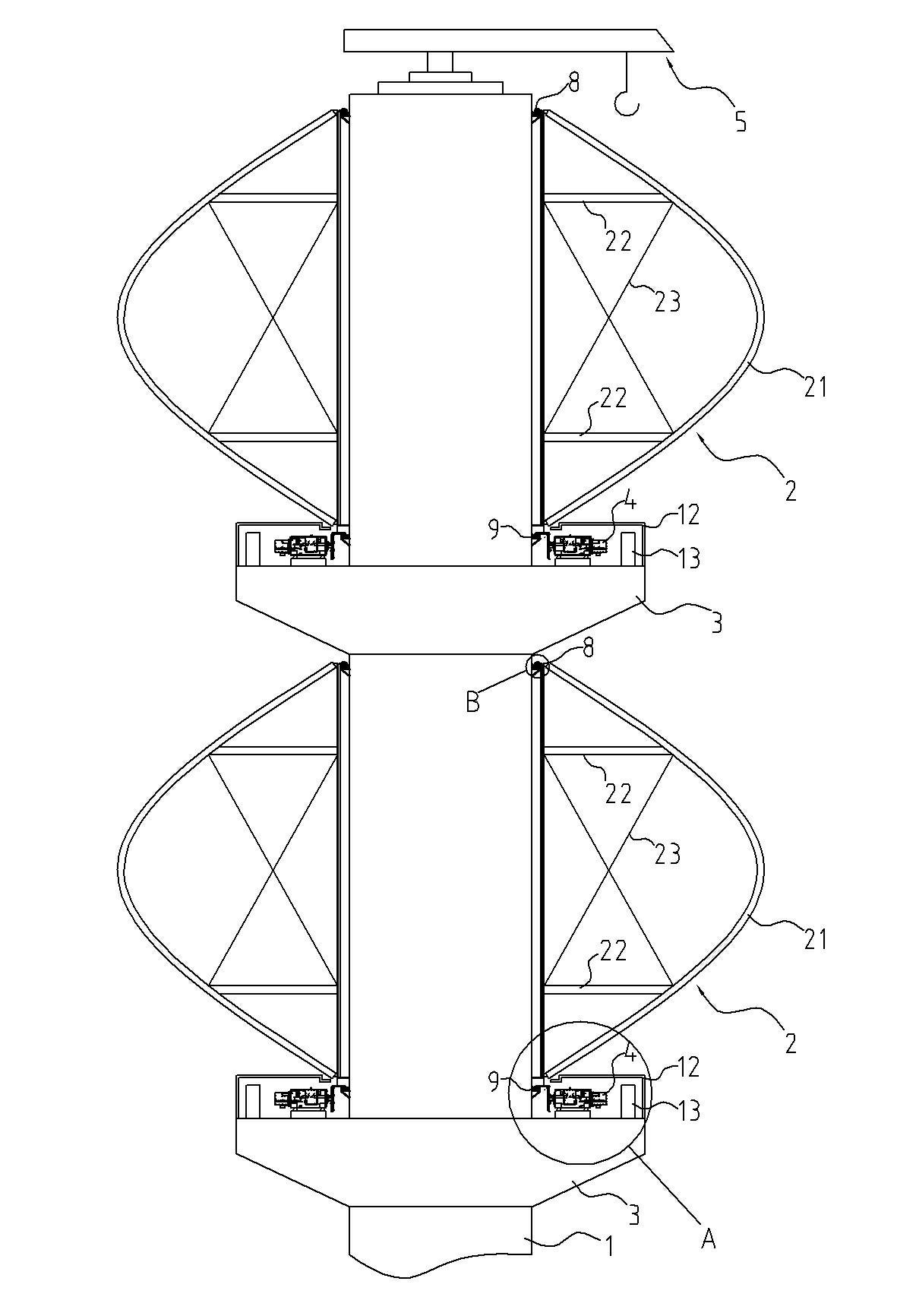
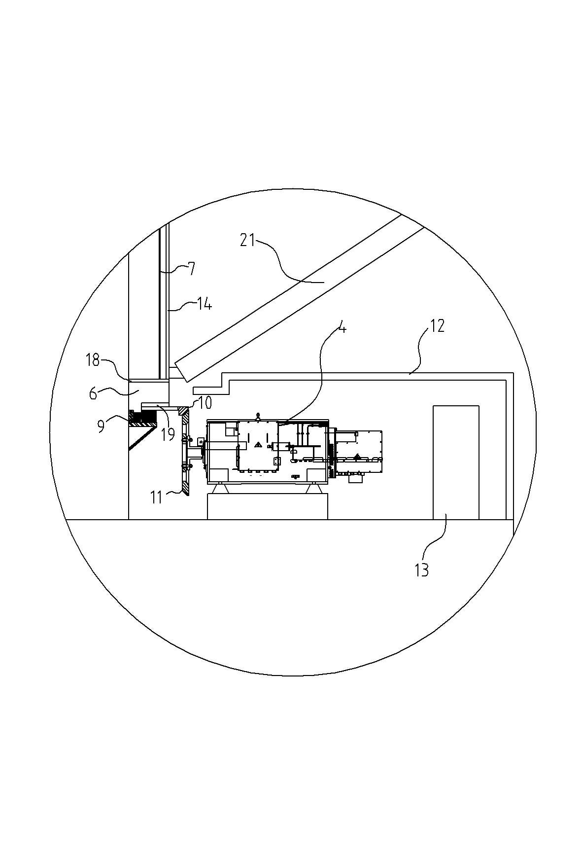
[0042] Such as figure 1 As shown, a vertical axis wind power generator includes a central tower column 1 on which more than two power generation units are arranged. In this embodiment, the central tower column 1 is a hollow reinforced concrete center A tower column 1, the central tower column 1 is provided with two power generation units arranged up and down. The power generation unit includes a wind wheel 2 , a main gear 10 , and more than two generators 4 . In this embodiment, two generators 4 are arranged symmetrically around the main gear 10 ; the wind wheel 2 is a Φ-shaped wind wheel, and the wind wheel 2 is composed of two symmetrically arranged blades 21 . Such as image 3 , 4 As shown, the central tower 1 is provided with a first bearing 8 corresponding to the upper end of the wind wheel 2 , and the central tower 1 is provided with a second bearing 9 corresponding to the lower end of the wind wheel 2 . The upper end of the blade 21 is connected to the outer ring of...

Embodiment 2

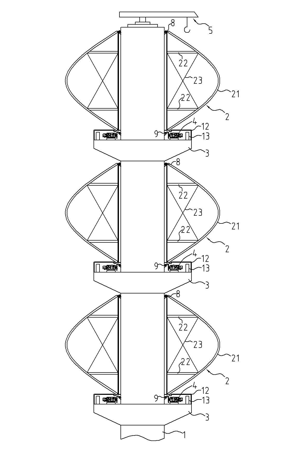
[0065] This embodiment is basically the same as Embodiment 1, except that three power generation units arranged up and down are arranged on the central tower.

[0066] In addition, in the above-mentioned embodiments 1 and 2, the gear transmission system can also be any other combination of gears that can play a transmission role. For example, the gear transmission system includes a pinion, a worm gear and a The pinion is engaged, the shaft of the pinion is provided with a worm gear, and the shaft of the generator 4 placed horizontally is provided with a worm, and the pinion is connected with the shaft of the generator 4 through the structure of the worm gear and worm. The vertical rotation of the wheel 2 is transformed into the horizontal rotation of the generator 4, and for the vertical axis wind power generator 4, the installation of the generator 4 is simpler and more convenient.

[0067] The reinforced concrete central tower column adopted by the invention is convenien...


PUM


Abstract

The invention discloses a field installation method for a vertical-shaft wind-driven generator. The method comprises the following steps of: (1) constructing a bottom base of a central tower column; (2) constructing a reinforced concrete central tower column on the bottom base; (3) installing a crane on the top of the central tower column; and (4) constituting a generating unit by using each installation platform, a generator, a wind wheel and generating equipment, and hoisting all generating units from top to bottom in sequence by using the crane. Each generating unit is hoisted by using the crane according to the following steps of: (a) hoisting a blade onto the central tower column; (b) hoisting a shaft coupling onto the central tower column and connecting with the wind wheel; (c) hoisting a main gear onto the central tower column and connecting with the shaft coupling; and (d) hoisting the generator and the generating equipment onto the installation platform, and meshing the generator with the main gear through a gear transmission system. Due to the adoption of the method, the vertical-shaft wind-driven generator is convenient to install and debug, the installation period is short, and the installation cost is low.

Description

technical field [0001] The invention relates to a field installation method of a wind power generator, especially a vertical axis wind power generator. Background technique [0002] As we all know, wind turbines include two types of horizontal axis and vertical axis, and their power generation principles are basically the same. The power generation efficiency is related to the wind speed and the effective wind energy utilization area of ​​the wind rotor. Simply put, the larger the wind rotor, the higher the power generation efficiency. After years of development, horizontal-axis wind turbines have been better developed than vertical-axis wind turbines. The wind rotors of horizontal axis wind turbines have a higher utilization rate of wind energy than those of vertical axis wind turbines. After years of research on the horizontal axis wind turbine, it can be said that it has reached the bottleneck of technology, and it is difficult to make a major breakthrough. Due to the la...

Claims


Application Information

Patent Timeline
Patent Type & Authority Applications(China)
IPC IPC(8): F03D11/04F03D3/00
CPCF03D3/02F05B2240/212F05B2230/61F03D11/04Y02E10/728Y02E10/74F03D13/20F03D13/22F03D13/25Y02P70/50
Inventor 邓允河
Owner GUANGZHOU YATU NEW ENERGY TECH
Why Eureka
Try Eureka