Supercharge Your Innovation With Domain-Expert AI Agents!

Broadband E surface omni-directional antenna based on circular waveguide TE01 mode

An omnidirectional antenna and circular waveguide technology, applied in leaky waveguide antennas, antennas, electrical components, etc., can solve the problems of antenna radiation efficiency reduction, unsuitability, high processing technology and precision requirements, and achieve the effect of small loss and simple structure

Inactive Publication Date: 2012-04-25
中国兵器工业第二〇六研究所
View PDF4 Cites 1 Cited by
  • Summary
  • Abstract
  • Description
  • Claims
  • Application Information

AI Technical Summary

Problems solved by technology

The main limitation of this implementation is that the radius of the circular array is limited by the power distribution network, and it is difficult to make it very small, so its omnidirectional performance is often not good, that is, the fluctuation of the radiation power amplitude in different directions is relatively large
Since the microstrip form is mostly used, when the antenna operating frequency is high, the processing technology and precision requirements are high, and the radiation efficiency of the antenna is significantly reduced, so it is not suitable for use at frequencies above the K-band

Method used


Image

  • Broadband E surface omni-directional antenna based on circular waveguide TE01 mode
  • Broadband E surface omni-directional antenna based on circular waveguide TE01 mode
  • Broadband E surface omni-directional antenna based on circular waveguide TE01 mode

Examples


Embodiment 1

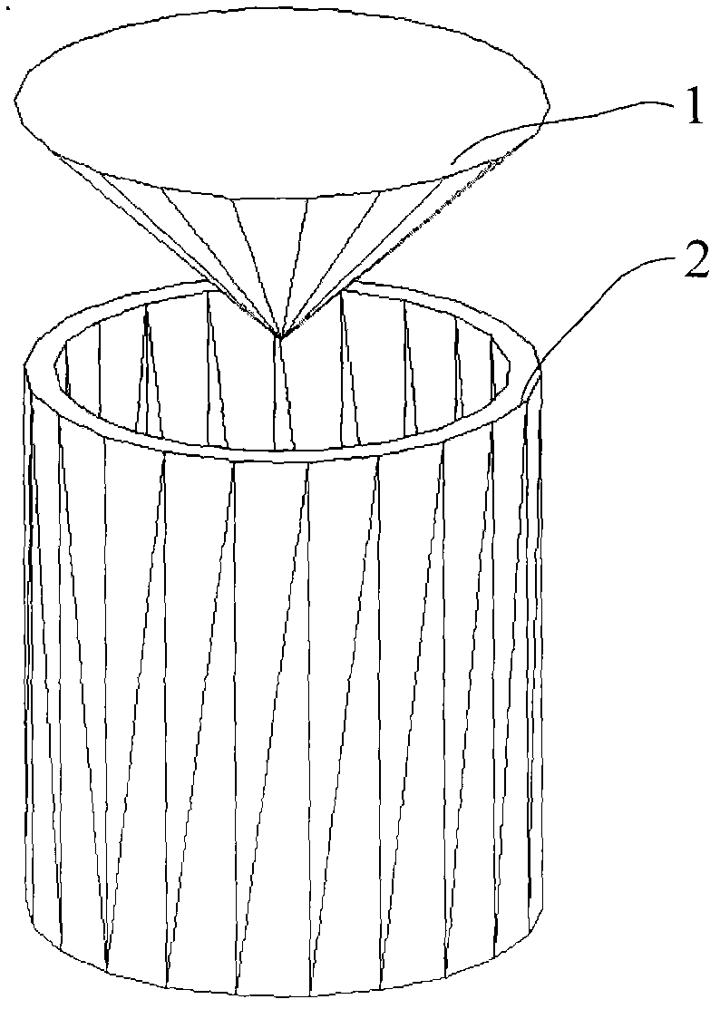
[0018] Such as figure 1 As shown, 1 is a tapered metal reflector, and 2 is a circular waveguide. The conical reflective surface can be supported by foam material, and for the convenience of understanding, the foam material for support is not shown in the figure.

[0019] The antenna characteristic that this embodiment requires to realize is: E face (namely figure 1 in the horizontal plane) omnidirectional radiation, H plane (ie figure 1 The elevation plane in ) the maximum radiation direction is in the horizontal direction. In order to achieve the required antenna characteristics, a conical reflector is used, and the operating frequency of the antenna is 26GHz-33GHz. figure 1 The structural parameters of the omnidirectional antenna are: the inner radius of the circular waveguide 2 is 7mm, the radius of the upper bottom of the cone 1 is 10mm, the height of the cone is 5mm, the distance between the top of the cone and the center of the circular waveguide opening is 4mm, and t...

Embodiment 2

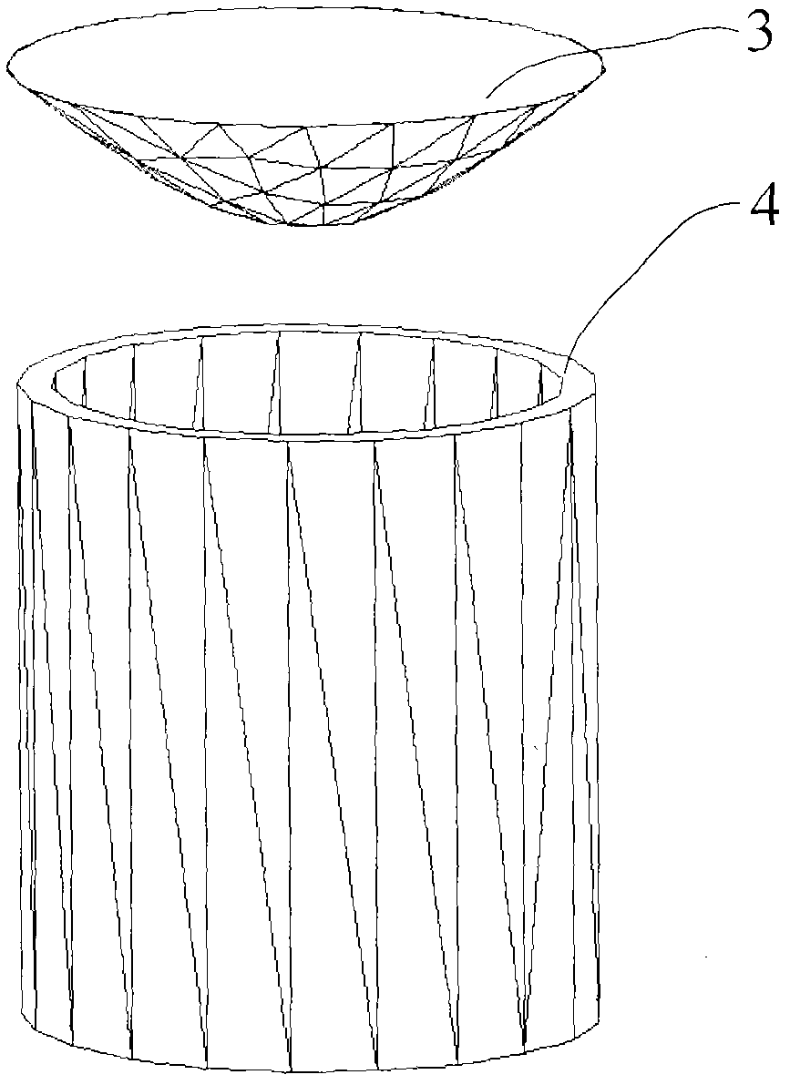
[0021] Such as figure 2 As shown, 3 is the metal rotating surface with the convex direction facing the waveguide opening, and 4 is the circular waveguide. The metal rotating surface can be supported by foam material, and for the convenience of understanding, the foam material for support is not shown in the figure.

[0022] The main component of the mode transmitted in the circular waveguide 2 should be the TEO1 mode (the power of the TEO1 mode accounts for more than 80% of the total transmission power). The specific parameters of the omnidirectional antenna are that the inner diameter of the waveguide is still 7mm, and the radius of the bottom surface of the metal rotating surface 3 is still 10mm, the height is still 5mm, the distance between the apex of the metal rotating surface and the center of the waveguide opening is still 4mm, and the parameter equation of the generatrix of the rotating surface is: y=x 2 / 20, such as Figure 5 As shown, 7 in the figure represents th...

Embodiment 3

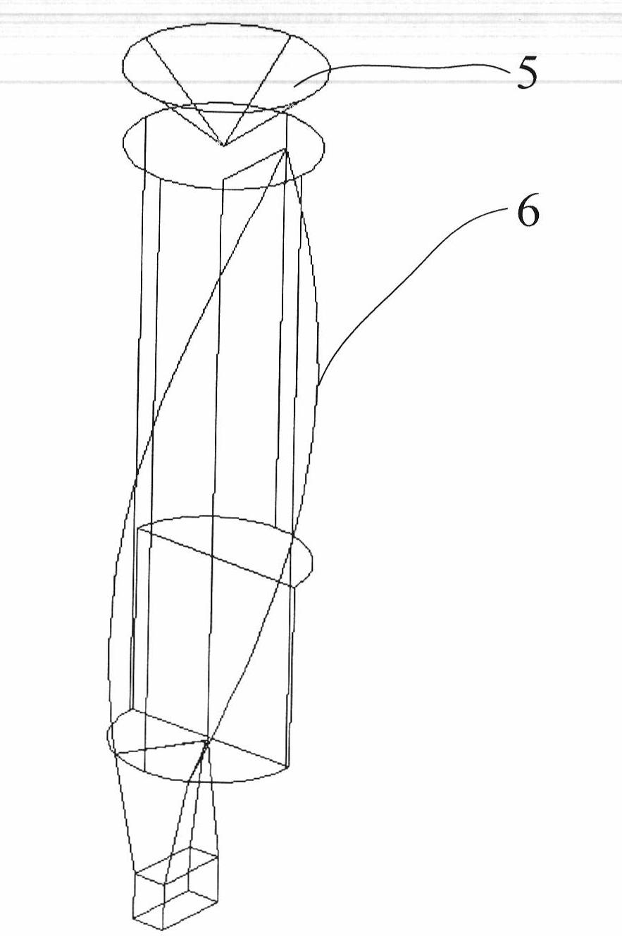
[0024] In the case that the microwave source outputs a non-circular waveguide TEO1 mode, a TEO1 mode converter can be used to convert the output mode of the microwave source into a circular waveguide TEO1 mode, and then use the antenna described in this patent, such as image 3 As shown, 5 in the figure is a mode converter from a rectangular waveguide to a circular waveguide TEO1 mode, and 6 is a metal tapered reflector.

[0025] On the premise that the circular waveguide transmits the TEO1 mode, adjusting the geometric parameters of the conical surface or rotating surface can achieve other technical indicators of the antenna (such as port impedance matching characteristics, H-plane beam characteristics, etc.) on the premise of obtaining omnidirectional radiation in the horizontal direction. Require. The main geometric parameters of the cone surface include: the height from the top to the waveguide, the diameter of the upper bottom surface, and the height of the cone; for the ...


PUM


Abstract

The invention relates to a broadband E surface omni-directional antenna based on a circular waveguide TE01 mode. A rotary symmetrical characteristic of the circular waveguide TE01 mode is utilized; and an opening circular waveguide that is used for transmitting the TE01 mode is used to irradiate a metal reflection plane and omnidirectional radiation of the broadband on an E surface of a directional diagram is realized. The appearance of the metal reflection plane is a tapered reflection plane or a rotary surface; when the rotary surface is selected, a projection direction of the rotary surface is headed to the opening of the circular waveguide. On the condition that a microwave source output is a non-circular waveguide TE01 mode, a TE01 mode converter is used to convert the microwave source output mode into a circular waveguide TE01 mode; and then, the TE01 mode is utilized to irradiate a metal reflection plane, so that omnidirectional radiation of a broadband on an E surface of a directional diagram is realized. 80% of power components of a waveguide mode transmitted in the opening circular waveguide is a TE01 mode. The antenna is suitable for application in a high frequency band including frequencies of over an S waveband and especially for application to frequencies of over a K wave band; and especially, an antenna bandwidth that is greater than 20% can be realized.

Description

technical field [0001] The invention belongs to the technical field of antennas, and in particular relates to a broadband E-plane omnidirectional antenna based on a circular waveguide TEO1 mode, which is used to realize E-plane omnidirectional radiation. technical background [0002] The E plane of the antenna refers to the plane formed by the maximum radiation direction of the antenna and the direction of the electric field in this direction. The so-called E-plane omnidirectional antenna means that on the E-plane, at the same distance from the antenna, the power of the antenna radiated (or received) signals is roughly the same. The concept corresponding to the E-plane omnidirectional is the H-plane omnidirectional, and the H-plane omnidirectional antenna is easy to implement, such as a whip antenna, while the E-plane omnidirectional antenna is more difficult to implement. Currently known methods for realizing omni-directional antennas on the E-plane include: [0003] 1. R...

Claims


Application Information

Patent Timeline
Patent Type & Authority Applications(China)
IPC IPC(8): H01Q13/20H01Q19/13H01Q15/16
Inventor 马汉清
Owner 中国兵器工业第二〇六研究所
Features
  • R&D
  • Intellectual Property
  • Life Sciences
  • Materials
  • Tech Scout
  • Unparalleled Data Quality
  • Higher Quality Content
  • 60% Fewer Hallucinations
Learn More