Method for detecting initial position of rotor of gearless tractor for elevator

A technology of rotor initial position and gear traction machine, which is applied in the control of generators, electronic commutators, motor generators, etc., and can solve problems such as out of control and misjudgment of control systems

Inactive Publication Date: 2012-04-25
HARBIN INST OF TECH
View PDF3 Cites 14 Cited by
  • Summary
  • Abstract
  • Description
  • Claims
  • Application Information

AI Technical Summary

Problems solved by technology

[0006] In order to solve the problem that the existing auxiliary signal injection method is used to obtain the initial position information of the rotor of the elevator traction machine, which is prone to misjudgment and cause the control system to lose control, a method for detecting the initial position of the rotor of the elevator gearless traction machine is provided

Method used


Image

  • Method for detecting initial position of rotor of gearless tractor for elevator
  • Method for detecting initial position of rotor of gearless tractor for elevator
  • Method for detecting initial position of rotor of gearless tractor for elevator

Examples


specific Embodiment approach 1

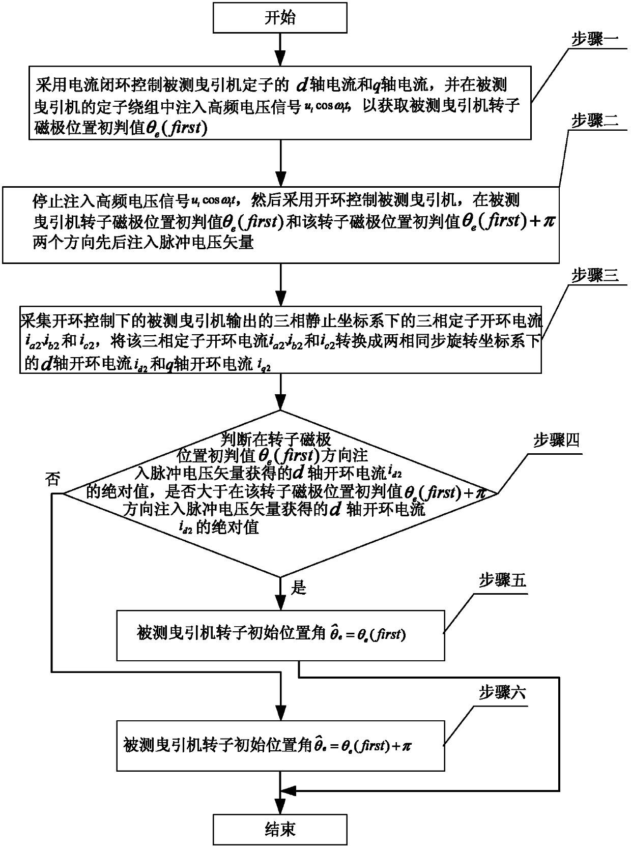
[0038] Specific implementation mode one: the following combination Figure 1 to Figure 5 Describe this embodiment, the method for detecting the initial position of the rotor of the elevator gearless traction machine described in this embodiment, the traction machine is a permanent magnet synchronous motor, and it includes the following steps:

[0039] Step 1: Use current closed-loop control of the d-axis current and q-axis current of the stator of the traction machine under test, and inject a high-frequency voltage signal u into the stator winding of the traction machine under test i cos ω i t, to obtain the initial judgment value θ of the rotor magnetic pole position of the tested traction machine e (first); where u i Indicates the amplitude of the high-frequency voltage signal, ω i Indicates the frequency of the high-frequency voltage, and t indicates the time;

[0040] Step 2: stop injecting high-frequency voltage signal u i cos ω i t, and then use open-loop control o...

specific Embodiment approach 2

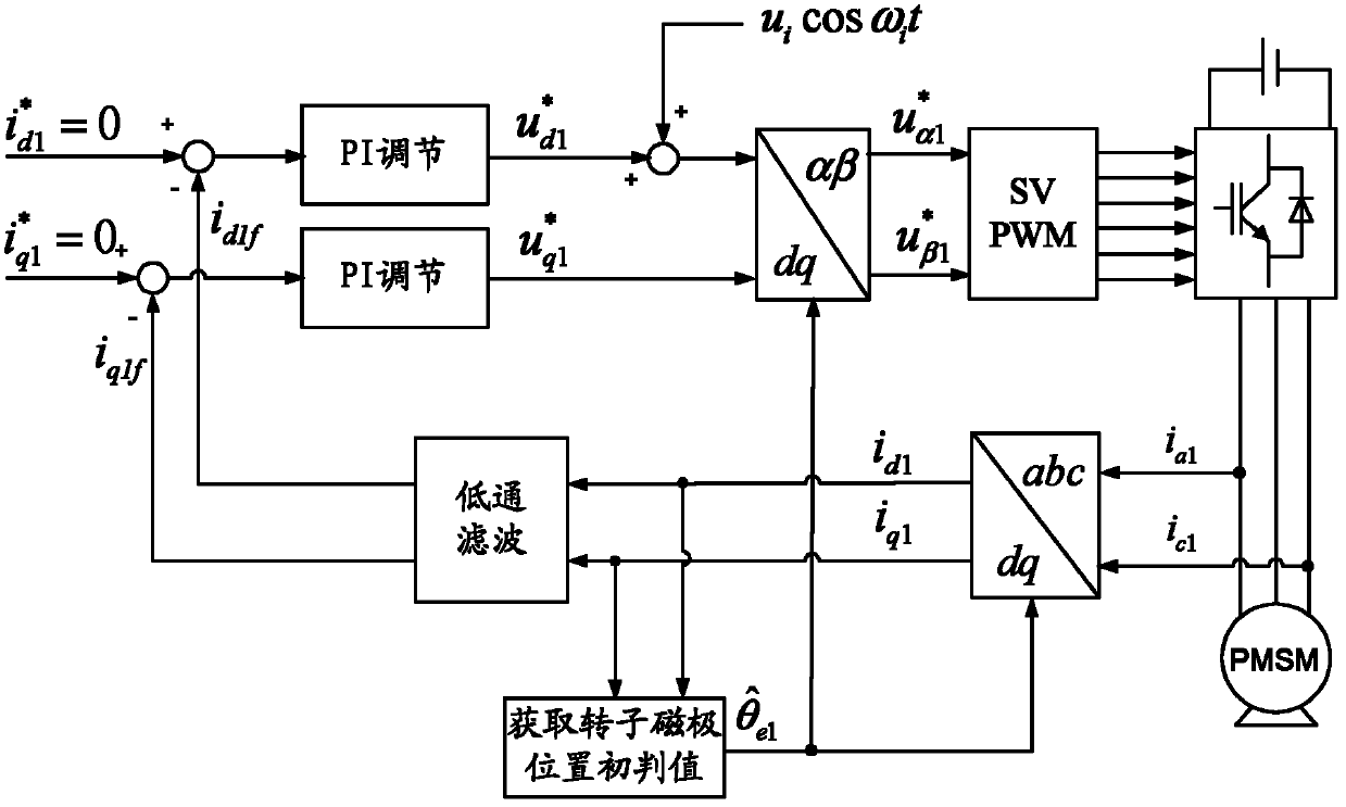
[0048] Specific implementation mode two: the following combination figure 2 , image 3 and Figure 4 Describe this embodiment. This embodiment is a further description of Embodiment 1. In step 1 of this embodiment, the initial judgment value θ of the rotor magnetic pole position of the measured traction machine is obtained. e The specific method of (first) is:

[0049] Step 11: Initialize the d-axis closed-loop given current of the stator of the traction machine under test q-axis closed-loop given current and the given position angle of the measured traction machine rotor Make it all 0;

[0050] Step 1 and 2: set the d-axis closed-loop current of the stator The d-axis closed-loop current feedback value i of the stator d1f After making a difference, the d-axis closed-loop given voltage of the stator is formed through PI adjustment The d-axis closed-loop given voltage with high frequency voltage signal u i cos ω i t is superimposed to form a stator d-axis close...

specific Embodiment approach 3

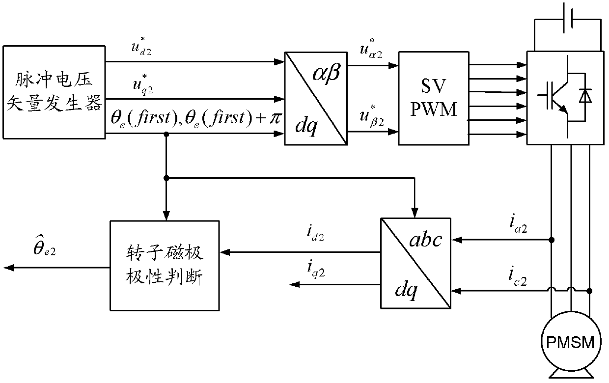
[0089] Specific implementation mode three: the following combination image 3 Describe this embodiment. This embodiment is a further description of Embodiment 1 or 2. The specific method of using open-loop control of the traction machine under test in step 2 of this embodiment is:

[0090] Using a pulse voltage vector generator to form a two-phase synchronous rotating coordinate system for the stator d-axis open-loop given voltage and stator q-axis open-loop given voltage And the stator d-axis open-loop given voltage and stator q-axis open-loop given voltage Convert the two-phase synchronous rotating coordinate system to the two-phase stationary coordinate system to obtain the stator voltage reference value in the two-phase stationary coordinate system and The stator voltage reference and The control of the traction machine under test is realized through the output of the three-phase inverter bridge to the traction machine under test, and the three-phase inverter...


PUM


Abstract

The invention discloses a method for detecting initial position of a rotor of a gearless tractor for an elevator. According to the method, the problem that when adopting an auxiliary signal injection method to obtain the initial position information of the rotor of the gearless tractor for the elevator at present, misjudging is easy to make so as to cause a control system to be out of control, is solved. The method comprises the steps of: firstly, obtaining the initial judge value [theta]e (first) of the rotor pole position of the tractor to be detected; then successively injecting pulse voltage vector into two directions, wherein one direction is in the angle of the initial judge value [theta]e (first) of the rotor pole position of the tractor to be detected and the other direction is in the angle of the sum of the initial judge value [theta]e (first) of pol position of the rotor with [pi]; obtaining d-shaft open loop current id2 and q-shaft open loop current iq2 of the tractor to be detected under a two-phase synchronous revolution coordinate system; judging the sizes of two id2 after the pulse voltage is injected; and obtaining the initial position angle of the rotor for the tractor to be detected by computing. The method for detecting initial position of rotor of gearless tractor for elevator is suitable for detecting the initial position of the rotor of the tractor for the elevator.

Description

technical field [0001] The invention relates to a method for detecting the initial position of a rotor of an elevator gearless traction machine, belonging to the technical field of motor control. Background technique [0002] With the continuous increase of high-rise buildings, elevators have become an indispensable means of vertical transportation, which puts forward higher requirements on the performance of the elevator speed control system. Compared with AC asynchronous motors, permanent magnet synchronous traction machines used in elevator traction systems have the characteristics of simple structure, space saving, high system efficiency and good control performance. The significance of energy saving becomes more prominent. Therefore, the traction system using permanent magnet synchronous motors has become the mainstream of the development of new elevator systems. [0003] With the continuous development of traction permanent magnet synchronous motor control technology...

Claims


Application Information

Patent Timeline
Patent Type & Authority Applications(China)
IPC IPC(8): H02P6/16H02P21/32
Inventor 王高林于泳杨荣峰徐殿国吴芳张国强李刚
Owner HARBIN INST OF TECH
Why Eureka
Try Eureka