Cold precision forging process for bevel gear and mould thereof

A cold precision forging and bevel gear technology, applied in the bevel gear processing technology and its mold field, can solve the problems of low production efficiency, large material waste, poor mechanical properties, etc., and achieve large mold loss, high dimensional accuracy, and no cutting loss. Effect

Inactive Publication Date: 2012-05-02
ZHEJIANG UNIV OF TECH
View PDF8 Cites 25 Cited by
  • Summary
  • Abstract
  • Description
  • Claims
  • Application Information

AI Technical Summary

Problems solved by technology

[0004] In order to overcome the disadvantages of low production efficiency, large material waste, high cost and poor mechanical properties of existing bevel gears in the mechanical cutting process, the present invention provides a high production efficiency, reduced material waste, and reduced cost. , Bevel gear cold precision forging process and its mold to improve mechanical properties

Method used


Image

  • Cold precision forging process for bevel gear and mould thereof
  • Cold precision forging process for bevel gear and mould thereof
  • Cold precision forging process for bevel gear and mould thereof

Examples


Embodiment 1

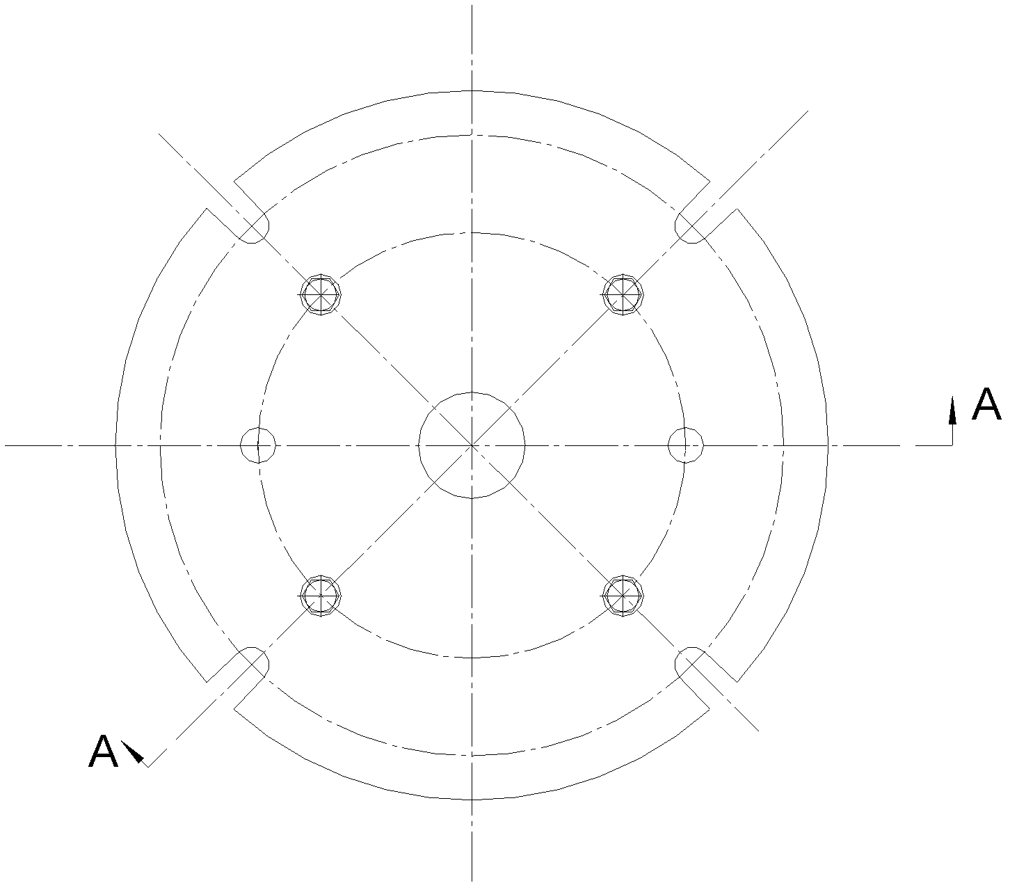
[0027] refer to Figure 1 to Figure 5 , a bevel gear cold precision forging process, the bevel gear cold precision forging process comprises the following steps:

[0028] 1) Use cylindrical bar material to cut and blank;

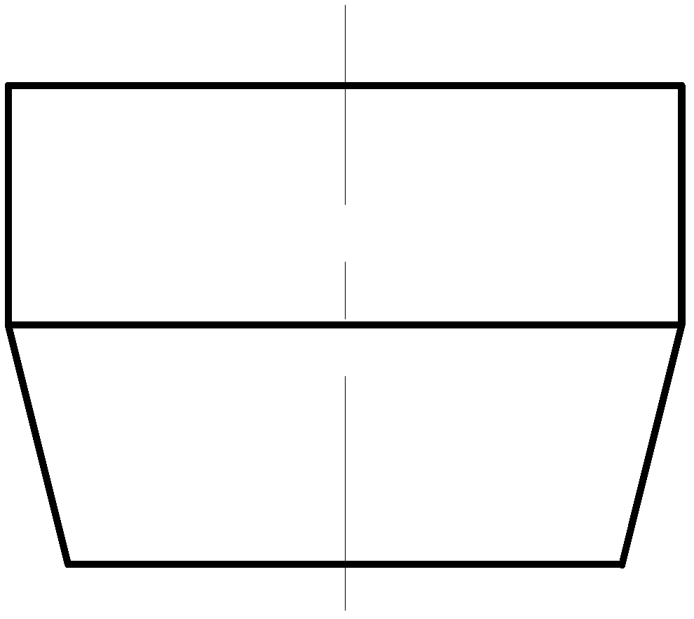
[0029] 2) Turning a taper on the length of the part of the blank as part of the pre-forming, the pre-forming is used for positioning the blank in the die;

[0030] 3) Carry out spheroidizing annealing to the machined blank to reduce its hardness, then pickling to remove scale, phosphating and saponification lubrication treatment;

[0031] 4) The first cold precision forging process: Upsetting and extruding part of the tooth shape in the extrusion die to obtain the first extrusion, which is used as the blank of the second cold precision forging process;

[0032] 5) performing spheroidizing annealing on the first extruded piece again, then pickling to remove scale, phosphating and saponification lubrication treatment;

[0033] 6) The second cold precision f...

Embodiment 2

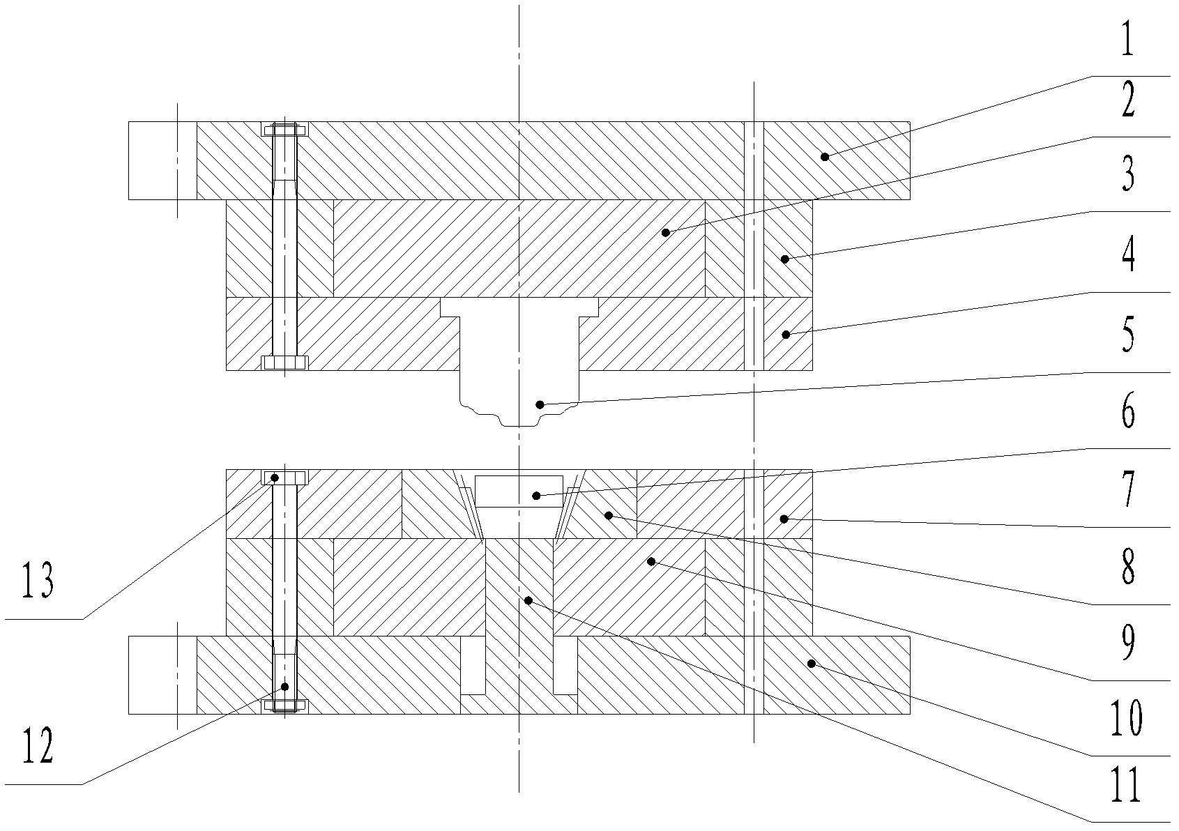
[0039] refer to figure 1 and figure 2 , a bevel gear cold precision forging die, the die includes a punch mechanism and a die mechanism, the punch mechanism is composed of an upper template 1, a punch pad 2, a punch ring 4 and a punch 5, the punch 5 is fixedly connected with the punch ring 4, the punch ring 4 is fixed on the punch pad 2, the punch ring 2 is fixedly connected with the upper template 1, and the upper template 1 is linked with the press; the die mechanism It is composed of die ring 7, die insert 8, die pad 9, lower template 10 and ejector rod 11. The die ring 7 is assembled with the die insert 6 for placing the blank 6 to be processed. , the die press ring 7 and the die insert 8 are fixed on the die pad 9, the die press ring 7 and the die pad 9 are fixedly connected with the lower template 10; the ejector rods 11 pass through the lower template in turn 11. The through hole in the middle of the matrix pad 9; the upper template 1 or the lower template 10 can be ...


PUM


Abstract

A cold precision forging process for a bevel gear is disclosed, and comprises the steps of: cutting the blanking by cylindrical bars; cutting a conical degree on a segmental length of the blank as segmental pre-form for positioning the blank in a die; performing spheroidization for the machined blank to reduce the hardness, then scouring and descaling, phosphorizing, saponifying and lubricating; the first cold precision forging step comprises: upsetting-extruding segmental tooth form in an extrusion mould to obtain a first extrusion which is used as the blank of the second first cold precision forging step; performing spheroidization again for the first extrusion, then scouring and descaling, phosphorizing, saponifying and lubricating; the second cold precision forging step comprises: upsetting-extruding all tooth forms in the extrusion mould to obtain the coarse material of the bevel gear; machining and shaping the coarse material of the bevel gear and cutting unnecessary materials on the end surface to obtain finished products of the bevel gear. The invention further provides an extrusion mould. The invention has higher production efficiency, reduces the material waste, lowers the cost and improves the mechanical property.

Description

technical field [0001] The invention relates to a bevel gear processing technology and a mold thereof. Background technique [0002] The traditional gear processing methods mainly include hobbing, shaping, shaving, grinding, grinding, grinding and polishing. The main feature of these methods is that relatively precise processing machine tools are used. Due to the mechanical cutting process, the tooth profile of the gear cannot be processed by the machine tool in one step, and the production efficiency is low, which is not conducive to the mass production of bevel gears; During the processing, due to the cutting action, it will inevitably lead to waste of materials, especially for expensive materials, the cost of materials will inevitably increase sharply; the metal fiber structure inside the unprocessed raw materials is naturally continuous and has good mechanical properties , and after machining, the metal fiber structure will inevitably be cut off, thereby reducing the me...

Claims


Application Information

Patent Timeline
Patent Type & Authority Applications(China)
IPC IPC(8): B21K1/30B21J13/02
Inventor 杨庆华孟彬潘隽
Owner ZHEJIANG UNIV OF TECH
Why Eureka
Try Eureka