
Method for manufacturing composite straightening roll by overlaying

A production method and a technology for straightening rolls, which are applied to welding media, manufacturing tools, welding equipment, etc., can solve the problems of unsatisfactory roll surface hardness, complex manufacturing process, and long production cycle, and achieve reduced manufacturing costs and surfacing welding smoke and dust. Less, the effect of shortening the production cycle

Active Publication Date: 2014-04-09
CHANGZHOU BAOLING HEAVY IND MACHINERY
View PDF5 Cites 0 Cited by
  • Summary
  • Abstract
  • Description
  • Claims
  • Application Information

AI Technical Summary

Problems solved by technology

[0003] The purpose of the present invention is to provide a solution to solve the problems of complex manufacturing process, high manufacturing cost, long production cycle, and roll surface hardness that cannot meet the application requirements of wide and thick plate straightening and leveling machines in the existing straightening rolls described in the background technology. A kind of manufacturing method of surfacing welding composite straightening roller

Method used


Image

  • Method for manufacturing composite straightening roll by overlaying
  • Method for manufacturing composite straightening roll by overlaying
  • Method for manufacturing composite straightening roll by overlaying

Examples


Embodiment 1

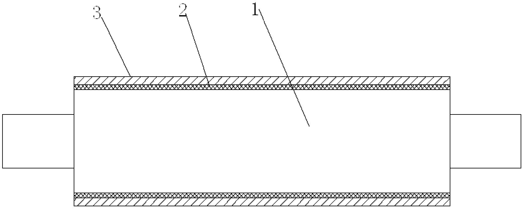
[0028] When producing straightening rolls, firstly manufacture the 42CrMo quenched and tempered straightening roll body 1, the straightening roll body should undergo quenching and tempering treatment, the tempering and quenching temperature is 840°C-880°C, and the tempering temperature is 550°C- 650℃, the surface hardness of the straightening roller body is HRC28-32, and the hardening depth is 30-40mm, and the quenching and tempering deformation is ≤1.5mm / m. Then build up a transition layer 2 of 2-4 mm on the straightening roller body 1; the deposited metal composition and mass percentage of the transition layer are: carbon≤0.12%, manganese 0.5-0.9%, silicon≤0.5%, nickel 0.8- 1.5%, phosphorus ≤ 0.025%, sulfur ≤ 0.020%, and iron as the balance, and then use welding wire submerged arc surfacing on the transition layer 2 to form a deposited metal working layer 3 with a thickness of 5-20mm. The composition and weight percentage of welding wire used in surfacing welding are: carbon...

Embodiment 2

[0033] On the basis of Example 1, as a more preferred embodiment, the composition and weight percentage of the deposited metal working layer 3 are: carbon: 0.37%, silicon: 0.43%, manganese: 0.52%, molybdenum: 0.41% , chromium: 5.67%, tungsten: 7.85%, vanadium: 0.27%, sulfur: 0.008%, phosphorus 0.012%, and the balance is iron; the thickness of the deposited metal working layer 3 is 10mm.

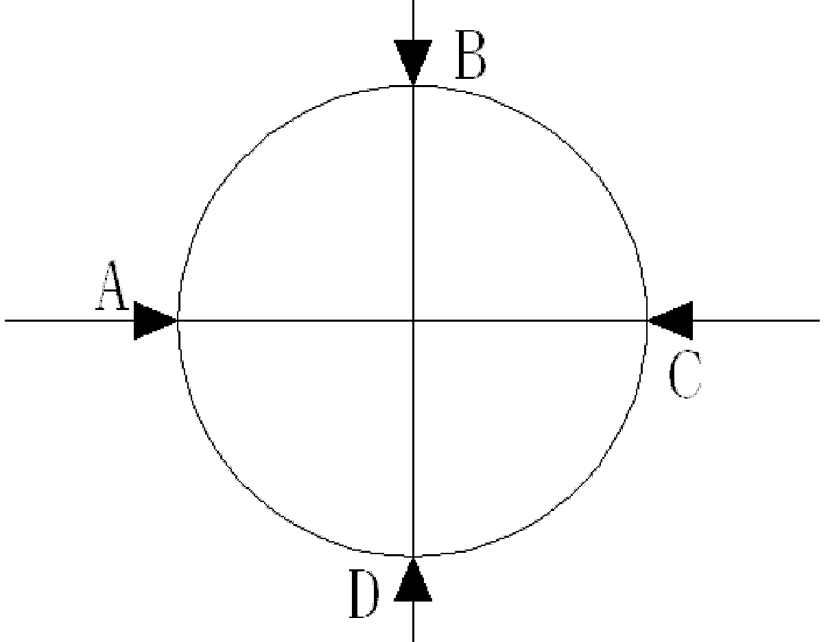
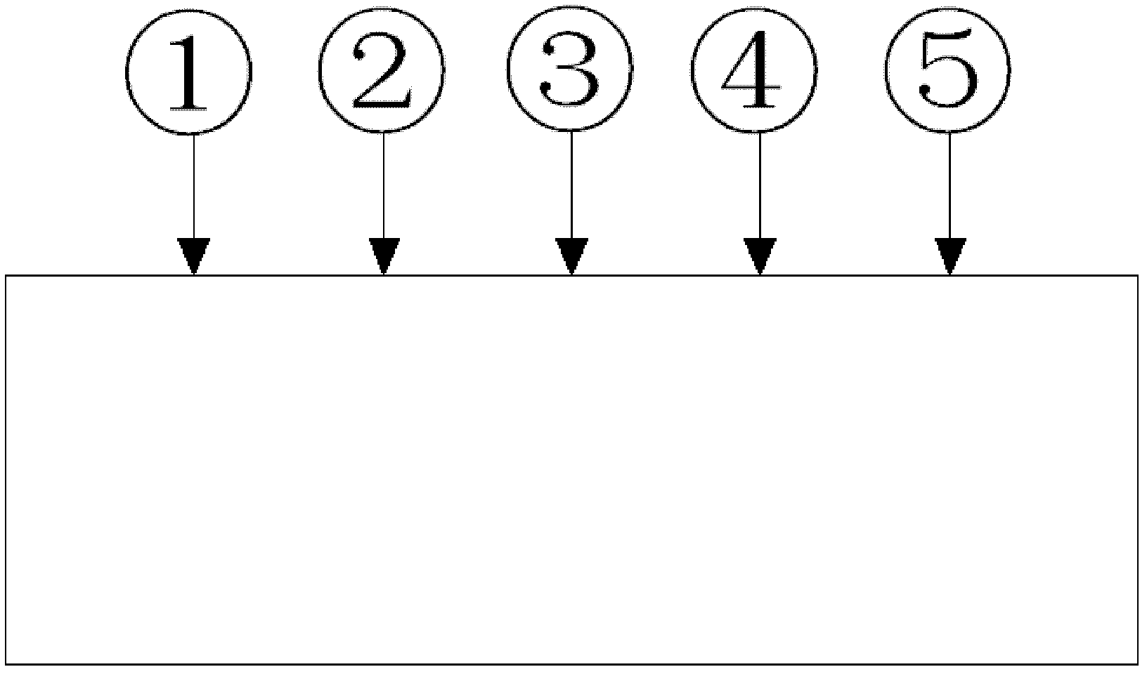
[0034] Such as figure 2 and image 3 The test points shown in , the hardness distribution of the product after 500℃×6h tempering treatment after surfacing welding, HRC

[0035]

Embodiment 3

[0037] On the basis of Example 1, as a more preferred embodiment, the composition and weight percentage of the deposited metal working layer 3 are: carbon: 0.35%, silicon: 0.40%, manganese: 0.50%, molybdenum: 0.42% , chromium: 6.0%, tungsten: 8.05%, vanadium: 0.25%, sulfur: 0.01%, phosphorus: 0.018%, and the balance is iron; the thickness of the deposited metal working layer 3 is 13mm.

[0038] Such as Figure 4 and Figure 5 The test points shown in , the hardness distribution of the product after 500℃×6h tempering treatment after surfacing welding, HRC

[0039]


PUM

PropertyMeasurementUnit
thicknessaaaaaaaaaa
thicknessaaaaaaaaaa
thicknessaaaaaaaaaa

Abstract

The invention discloses a method for manufacturing a composite straightening roll by overlaying, comprising the steps of: at first, manufacturing a straightening roller body tempered by 42 CrMo; then overlaying a transitional layer which is 2-4mm thick on the straightening roller body; and then manufacturing a deposited metal working layer on the transitional layer through submerged arc overlaying. The roll surface of the straightening roll manufactured by the method for manufacturing the composite straightening roll by overlaying has the advantages of corrosion resistance, high temperature resistance, abrasion resistance and steel adhering resistance.

Description

technical field [0001] The invention relates to the field of mechanical manufacturing, in particular to a method for manufacturing a surfacing welding composite straightening roller. The welding material and process method of the present invention can also be widely used in the surfacing welding compound of pinch rolls, hot rolling rolls and hot rolling support rolls on the rolling production line, in addition to being used for the straightening work rolls of the hot rolling skin pass mill It has the advantages of corrosion resistance, high temperature resistance, wear resistance and anti-sticking steel. Background technique [0002] With the technological transformation and product upgrading of iron and steel enterprises, their production capacity and product quality have been greatly improved. At the same time, the requirements for metallurgical equipment are also getting higher and higher; The key equipment for the production of wide and thick plates in iron and steel en...

Claims


Application Information

Patent Timeline
Patent Type & Authority Patents(China)
IPC IPC(8): B23K9/04B23K9/18B23K35/30
Inventor 孔念荣许崇山于光远
Owner CHANGZHOU BAOLING HEAVY IND MACHINERY
Learn More