Cooling device for direct reduction iron

A cooling device and technology for reducing iron, applied in the direction of processing discharged materials, lighting and heating equipment, furnace components, etc., to achieve the effect of reducing equipment weight, simple structure, and good sealing effect

Inactive Publication Date: 2012-05-02
李世杰 +1
View PDF8 Cites 11 Cited by
  • Summary
  • Abstract
  • Description
  • Claims
  • Application Information

AI Technical Summary

Problems solved by technology

[0003]At present, the cooling of the direct reduced iron in the world mainly adopts the spray type indirect water-cooled rotary drum, which is to put the hot reduced iron into the rotary drum in a closed state. Due to the thin water film on the cylinder and the part with hot material at the bottom of the cylinder, there is basically no water, so its cooling efficiency is poor; therefore, the technicians are forced to spray water in the tail cylinder to cool directly to complete the cooling, but the product Metallization rate decreased by 2-3%
Due to the poor cooling efficiency, the cooling cylinder 17 is manufactured with large and long specifications, generally 3 to 4 meters in diameter and 40 to 50 meters in length. The purpose is to prolong the cooling time, but it increases investment and operating costs.
In addition, the spray water vaporizes, seriously polluting the environment, especially in the cold northern regions, where the steam pollution is more serious
The technology is currently failing to improve optimization and has become old and outdated
[0004] In order to save costs, some small iron and steel metallurgical enterprises put hot reduced iron directly into water for quenching after being released from the furnace. As a result, the metallization rate is reduced by more than 5%, and the pollution is more serious Severe, dehydration is more troublesome

Method used


Image

  • Cooling device for direct reduction iron
  • Cooling device for direct reduction iron
  • Cooling device for direct reduction iron

Examples


Embodiment Construction

[0027] The present invention will be further described in detail below in conjunction with the accompanying drawings.

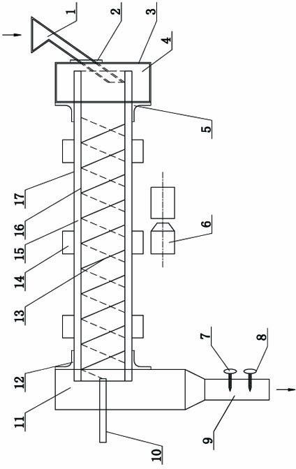
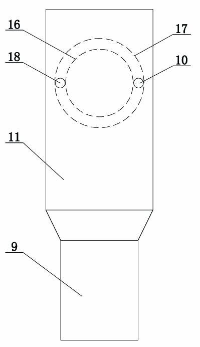
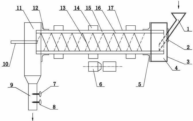
[0028] Such as figure 1 , figure 2 As shown, a cooling device for direct reduced iron includes a cooling cylinder 17, a ring gear 14 and a transmission device 6, the ring gear 14 is fixed on the outer circumference of the cooling cylinder 17, the ring gear 14 is connected with the transmission device 6, and the cooling cylinder One end of 17 is connected to the feed hopper 1, and the other end is connected to the kiln tail box 11. The end of the cooling cylinder 17 connected to the feed hopper 1 is provided with a kiln head box 4, and the outer circumference of the cooling cylinder 17 is arranged between the kiln head box 4. There is a head seal ring 5, a tail seal ring 12 is arranged between the outer circumference of the cooling cylinder 17 and the kiln tail box 11, an end seal ring 2 is arranged between the feed hopper 1 and the kiln head box 4, the hea...


PUM


Abstract

The invention relates to a cooling device for direct reduction iron. The cooling device comprises a cooling cylinder, wherein a gear ring is fixed on the outer circumference of the cooling cylinder; a transmission device is used for driving the gear ring to rotate; one end of the cooling cylinder is connected with a feeding hopper, and the other end of the cooling cylinder is connected with a kiln tail box; the lower end of the kiln tail box is provided with a discharging pipe; a water sleeve is fixed on the inner wall of the cooling cylinder; the discharging end of the feeding hopper is arranged in the water sleeve; a cooling water channel is formed between the outer wall of the water sleeve and the inner wall of the cooling cylinder; one end of the cooling water channel is provided a water inlet and a water outlet; and the inner wall of the water sleeve is provided with spiral fins. In the invention, a cooling cylinder shell is forcedly cooled by adopting water sleeve type high-speed water current, and the walking path of the direct reduction iron in the cylinder is controlled by using the spiral fins, so that the walking time of the direct reduction iron in the cylinder is prolonged, the cooling efficiency is greatly increased, the diameter and the length of the cooling cylinder are reduced, the equipment weight is greatly reduced, and the transmission power and power consumption of the equipment are lowered; and meanwhile, no steam is dissipated, so that the environmental pollution is improved greatly.

Description

Technical field: [0001] The invention belongs to the technical field of auxiliary equipment for iron and steel metallurgy, and in particular relates to a cooling device for high-temperature direct reduction iron. Background technique: [0002] High-temperature direct-reduced iron is produced in the iron and steel industry and non-ferrous metallurgical industry. The temperature is about 1200 ° C, and the metallization rate after reduction is 80-90%. Its temperature is high and cannot be conveniently transported and stored; When encountering air and water, it will be violently oxidized and burned, and the products that have been reduced to metallic iron and metallic nickel will be oxidized again to oxides, which cannot be used. Therefore, an indirect cooling device is needed to cool it below 100°C. [0003] At present, the cooling of direct reduced iron in the world mainly adopts spray-type indirect water-cooled rotary drum, which is to put hot reduced iron into the rotary ...

Claims


Application Information

Patent Timeline
Patent Type & Authority Applications(China)
IPC IPC(8): F27D15/02C21B13/00
Inventor 秦廷许李世杰李文龙
Owner 李世杰
Why Eureka
Try Eureka