
Anti-metal tag antenna applied in RFID (radio frequency identification device) system on UHF (ultra high frequency) band

An anti-metal tag, antenna technology, applied in antennas, antenna supports/installation devices, devices that make antennas work in different bands at the same time, etc., can solve the problems of good bandwidth, low gain, high gain, narrow bandwidth, etc. Small, increased antenna gain, simple structure

Inactive Publication Date: 2012-05-02
BEIJING UNIV OF POSTS & TELECOMM
View PDF0 Cites 21 Cited by
  • Summary
  • Abstract
  • Description
  • Claims
  • Application Information

AI Technical Summary

Problems solved by technology

At present, the reading distance of the existing planar structure tag antennas that can be applied to metal backgrounds is generally within 10m. The existing antennas either have good bandwidth and low gain, or high gain and narrow bandwidth.

Method used


Image

  • Anti-metal tag antenna applied in RFID (radio frequency identification device) system on UHF (ultra high frequency) band
  • Anti-metal tag antenna applied in RFID (radio frequency identification device) system on UHF (ultra high frequency) band
  • Anti-metal tag antenna applied in RFID (radio frequency identification device) system on UHF (ultra high frequency) band

Examples


Embodiment Construction

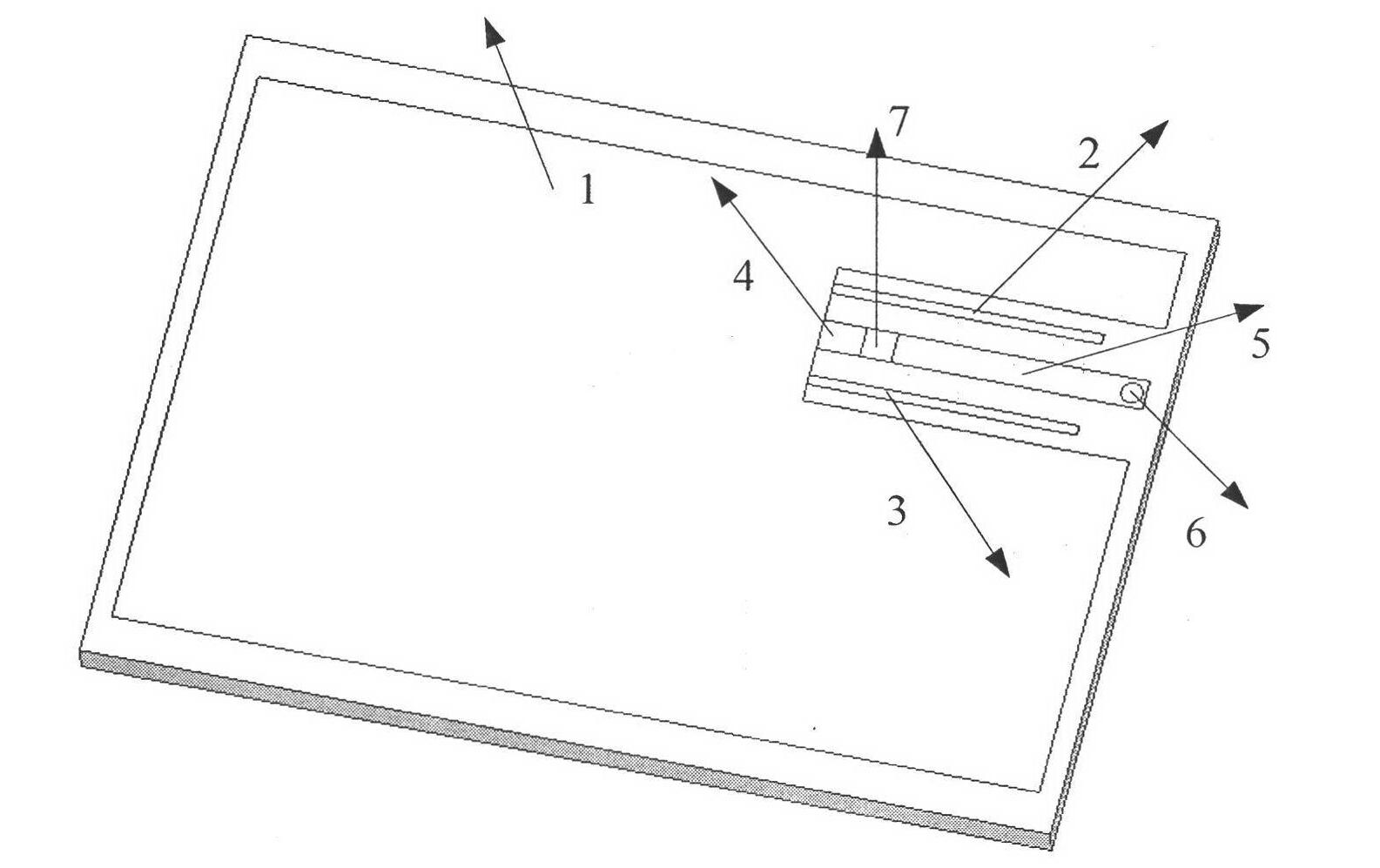
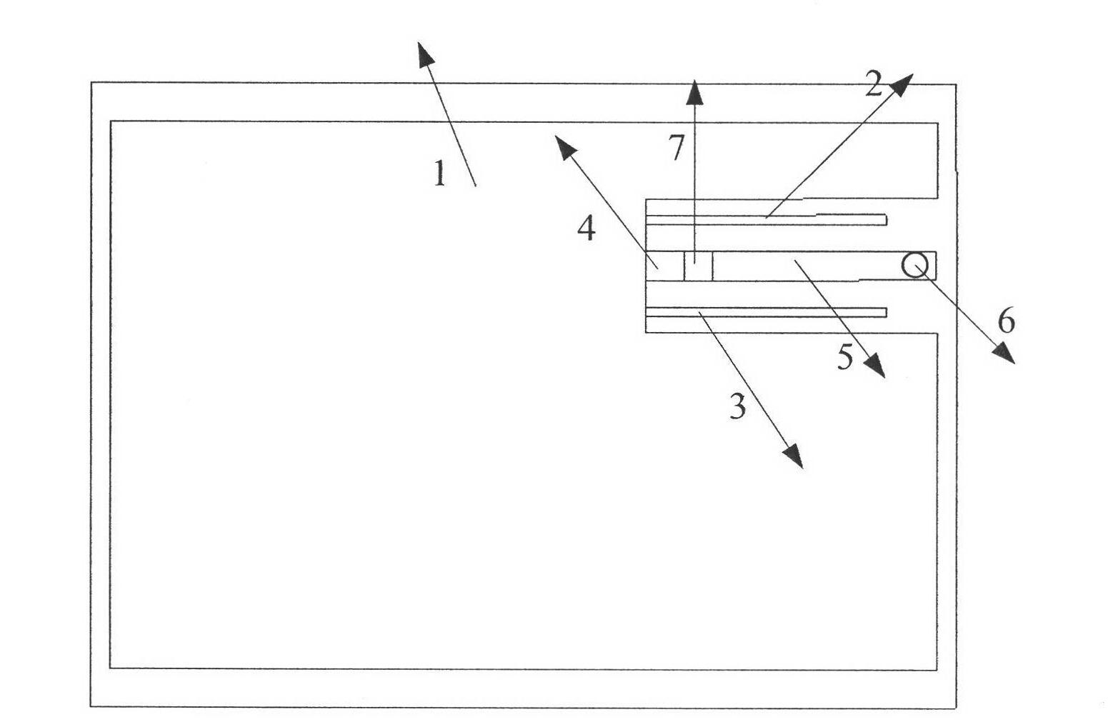
[0021] This solution is an anti-metal tag antenna that covers UHF radio frequency identification frequencies in the United States and is used in license plate recognition applications where the reading distance is greater than 16m. The tag antenna of the present invention realizes the design of the ultra-high frequency anti-metal tag antenna by using a short-circuit stub. The tag chip adopts the NXP G2 type ultra-high frequency radio frequency tag, and the impedance of the chip at 915MHz is (16-j*148) Ohm. The following describes in detail the anti-metal tag antenna of the present invention with reference to the accompanying drawings.

[0022] An anti-metal tag antenna of the present invention is applied to UHF frequency band RFID system. The antenna structure includes: 1. Radiation surface 2, open line 3, open line 4, second feeder 5, first feeder 6, metal via 7, tag chip . Grooves are formed between the radiation surface 1 and the feeders 4 and 5, and the resonant frequency...


PUM


Abstract

The invention relates to an anti-metal tag antenna applied in an RFID (radio frequency identification device) system on a UHF (ultra high frequency) band, relating to the technical field of a radio frequency identification type electronic tag. The antenna mainly comprises a metal substrate, a dielectric plate and an antenna structure. The antenna structure is arranged on the upper surface of the dielectric plate, the metal substrate is arranged on the lower surface of the dielectric plate, and the antenna structure is communicated with the metal substrate through metal through holes. The antenna structure mainly comprises an asymmetric metal radiating surface and an open circuit line, and the open circuit line is connected with the radiating surface and is arranged parallel to feeder lines. The feeder lines on the two sides of a chip are respectively connected with the metal radiating surface and the metal through holes. Since the radiating surface of the antenna is asymmetric, current paths are different, the dual-band approximation of the antenna to the same resonant point can be achieved, and the bandwidth of the antenna can be broadened. High gain and broad bandwidth can be achieved simultaneously, and the theoretical reading distance is more than 16m in the American frequency band from 902MHz and 928MHz. The anti-metal antenna can be applied in situations with large reading distances, such as license plate identification.

Description

technical field [0001] The invention relates to a radio frequency identification electronic tag, which is characterized in that it works in an ultra-high frequency band and is applied to a license plate. Background technique [0002] Radio Frequency Identification (RFID) is a technology that conducts non-contact two-way data communication through radio frequency to identify targets. The radio frequency identification system generally consists of a reader (Reader) and an electronic tag (Tag). The electronic tag is composed of an on-chip antenna and a chip, which exchanges data with the reader through electromagnetic waves, and has the functions of intelligent reading and writing and encrypted communication. The antenna is a crucial device in the RFID system. The RFID system transmits and receives electromagnetic waves through the radio frequency antenna, so as to realize the identification of the electronic tag by the reader. [0003] RFID systems mainly work in low frequen...

Claims


Application Information

Patent Timeline
Patent Type & Authority Applications(China)
IPC IPC(8): H01Q1/38H01Q5/01H01Q1/22H01Q5/10
Inventor 李秀萍徐婷婷李文勋邹琴张陈乾
Owner BEIJING UNIV OF POSTS & TELECOMM
Learn More