High-speed vision capture apparatus of moving object characteristic

A technology for visual capture and moving targets, applied in the field of high-speed visual capture devices for moving target features, can solve the problems of low transmission speed, large amount of data, low real-time processing speed, etc., and achieve the effect of improving processing speed

Active Publication Date: 2012-05-02
HARBIN INST OF TECH
View PDF5 Cites 27 Cited by
  • Summary
  • Abstract
  • Description
  • Claims
  • Application Information

AI Technical Summary

Problems solved by technology

[0004] The purpose of the present invention is to solve the problems of low real-time processing speed, large amount of data, and

Method used


Image

  • High-speed vision capture apparatus of moving object characteristic
  • High-speed vision capture apparatus of moving object characteristic
  • High-speed vision capture apparatus of moving object characteristic

Examples


specific Embodiment approach 1

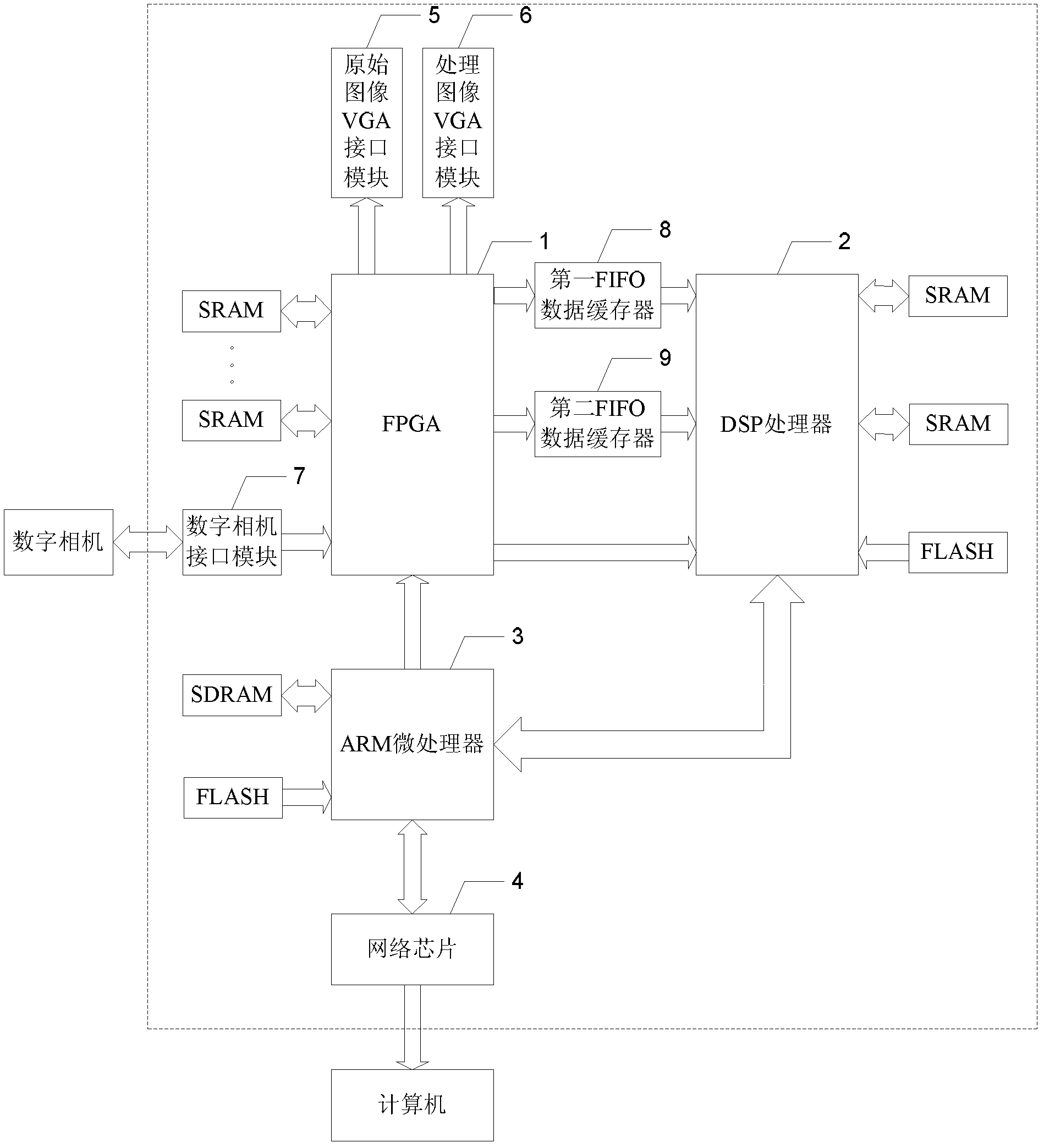
[0022] Specific implementation mode one: the following combination figure 1 , image 3 and Figure 4 Illustrate this embodiment, a kind of high-speed visual capture device of moving object feature described in this embodiment, it comprises FPGA1, DSP processor 2, ARM microprocessor 3, network chip 4, original image VGA interface module 5, processing image VGA interface Module 6, digital camera interface module 7, first FIFO data buffer 8 and second FIFO data buffer 9,

[0023] Digital camera gathers original image, and is connected with the image input end of FPGA1 by digital camera interface module 7, and the original image display output end of FPGA1 is connected with the input end of original image VGA interface module 5, and the processed image display output end of FPGA1 and processing The input end of the image VGA interface module 6 is connected, the first cache output end of FPGA1 is connected with the input end of the first FIFO data buffer 8, the output end of the ...

specific Embodiment approach 2

[0025]Specific implementation mode two: this implementation mode further explains implementation mode one, it also includes multi-chip SRAM, two slices of FLASH and one slice of SDRAM,

[0026] FPGA1 is provided with multiple storage input and output terminals, and each storage input and output terminal of FPGA1 is connected to the input and output terminals of a slice of SRAM;

[0027] The DSP processor 2 is provided with two storage input and output terminals, each storage input and output terminal of the DSP processor 2 is connected with the input and output terminals of a SRAM, and the cache input terminal of the DSP processor 2 is connected with the output terminal of the FLASH;

[0028] The storage input and output terminals of the ARM microprocessor 3 are connected with the input and output terminals of the SDRAM, and the cache input terminals of the ARM microprocessor 3 are connected with the output terminals of the FLASH.

[0029] Using the hardware structure of FPGA+...

specific Embodiment approach 3

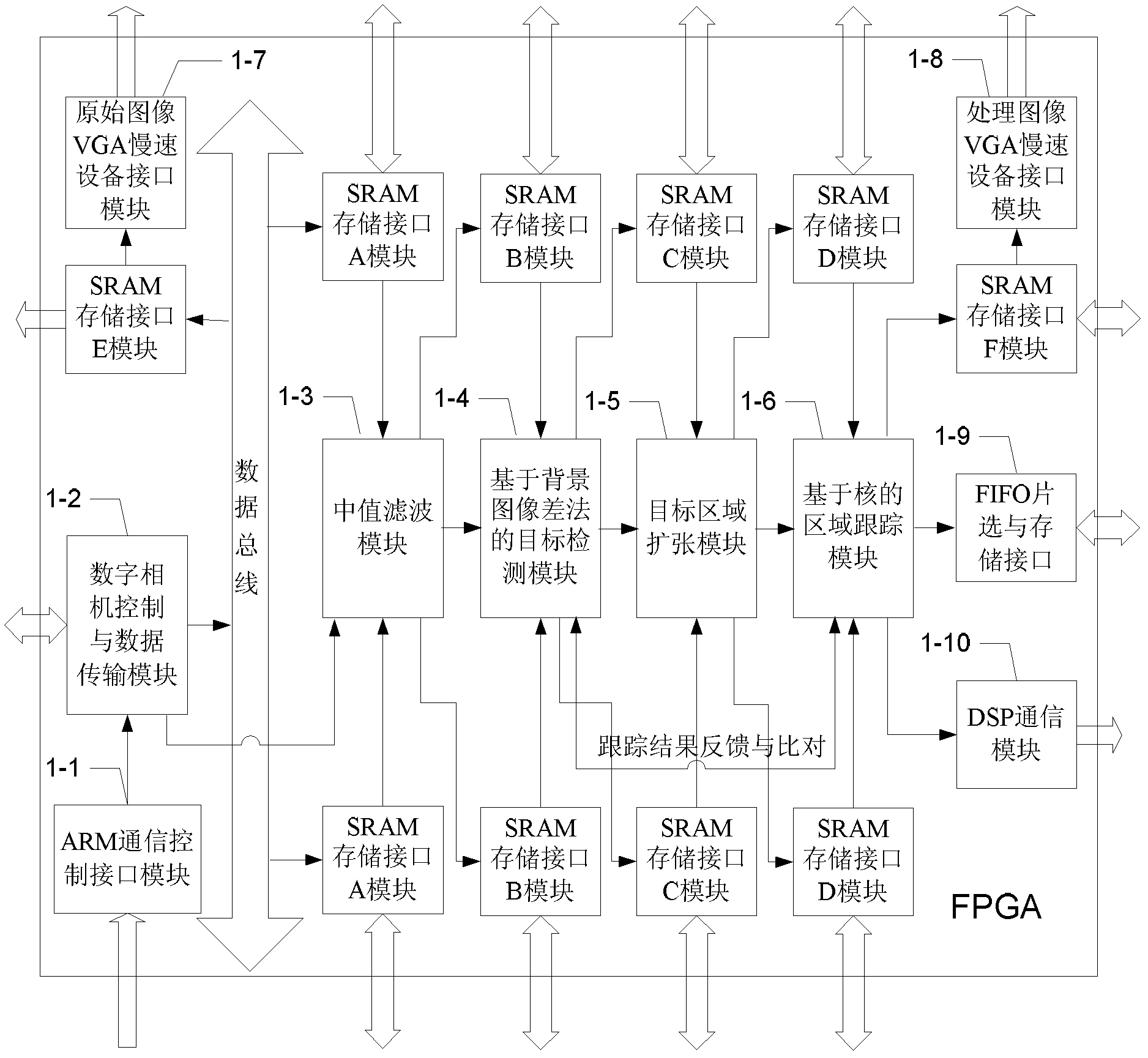
[0069] Specific implementation mode three: according to the following figure 2 Describe this embodiment, this embodiment further limits Embodiment 1 and 2, FPGA1 includes ARM communication control interface module 1-1, digital camera control and data transmission module 1-2, median filter module 1-3, based on the background Target detection module 1-4 of image difference method, target area expansion module 1-5, kernel-based area tracking module 1-6, original image VGA slow device interface module 1-7, processed image VGA slow device interface module 1 -8. FIFO chip selection and storage interface 1-9 and DSP communication module 1-10,

[0070]The control signal input end of the ARM communication control interface module 1-1 is connected with the control signal output end of the ARM microprocessor 3, and the control signal output end of the ARM communication control interface module 1-1 is connected with the digital camera control and data transmission module 1-2. The contro...


PUM


Abstract

A high-speed vision capture apparatus of a moving object characteristic belongs to the image processing field and the machine vision image measurement field. In the high-speed vision measurement, a real-time processing speed is not fast, a data volume is large and a transmission speed is low. By using the apparatus of the invention, the above problems can be solved. The apparatus comprises: a field-programmable gate array (FPGA), a digital signal processor (DSP), an advanced RISC machines (ARM) microprocessor, a network chip, an original image video graphics array (VGA) interface module, a processing image VGA interface module, a digital camera interface module, a first and a second first in first out (FIFO) data buffers. A digital camera collects an original image to the FPGA. The FPGA is connected with the original image VGA interface module and the processing image VGA interface module. A cached output terminal of the FPGA is connected with input terminals of the first and a secondFIFO data buffers respectively and is connected with the DSP. The DSP is connected with the ARM microprocessor. The ARM microprocessor is connected with a control signal input terminal of the FPGA. The ARM microprocessor is connected with a computer through the network chip.

Description

technical field [0001] The invention relates to a high-speed visual capture device for moving target features, which belongs to the field of image processing and machine vision image measurement. Background technique [0002] With the rapid development of military technology in various countries, a large number of high-speed moving targets, such as military aircraft and missiles, have appeared. The flight speed reaches Mach 3 or more, which poses a huge threat to national security. High-speed moving targets also exist in aerospace, traffic safety, military reconnaissance, shooting range testing, air target interception, mechanical research and other fields. At this stage, there is a need for a method that can capture, track and measure the position, pose and motion state of a high-speed moving target. [0003] The test method based on machine vision has the characteristics of non-contact, high precision, fast speed, and good stability. It is an effective method for measurin...

Claims


Application Information

Patent Timeline
IPC IPC(8): H04N5/77H04N5/14G06T7/20
Inventor 叶东于潇宇郭玉波陈刚赵振庆
Owner HARBIN INST OF TECH
Why Eureka
Try Eureka