Cam type assistance-adjustable hydraulic power-assisted steering system and control method thereof
A technology of hydraulic power steering and hydraulic power assist, applied in the direction of fluid steering mechanism, etc., can solve the problems of large battery load, floating, and insufficient portability, and achieve the effects of less power, simple structure, and little impact on service life.
- Summary
- Abstract
- Description
- Claims
- Application Information
AI Technical Summary
Problems solved by technology
Method used
Image
Examples
Embodiment 1
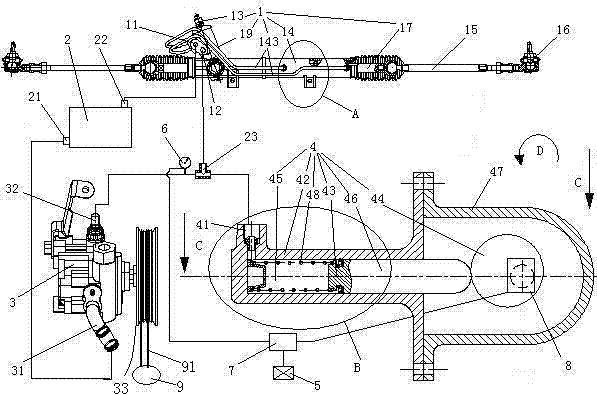
[0036] Example 1, see figure 1 , A cam type power assist adjustable hydraulic power steering system, including a steering pump 3, a reservoir 2, a hydraulic power steering gear 1, a power regulator 4, a vehicle speed sensor 5, a pressure sensor 6, a control unit 7 and a stepping motor 8. The vehicle speed sensor 5, the pressure sensor 6 and the stepping motor 8 are electrically connected to the control unit 7.
[0037] The control unit 7 is the ECU of the car itself.
[0038] The stepping motor 8 is a stepping motor with a locking function. No need to design a locking structure separately, simplifying the overall structure.
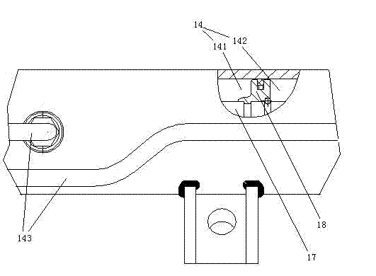
[0039] The steering pump 3 is a single-acting vane pump. The steering pump 3 is driven by the engine 9. The steering pump inlet 31 is connected with the outlet 21 of the storage tank through a pipeline, and the inlet 22 of the storage tank is connected with the outlet 11 of the hydraulic power steering device through a pipeline. The pump outlet 32 and the ...
Embodiment 2
[0051] Example two, see Figure 5 , The difference from the first embodiment is the boost regulator 4.
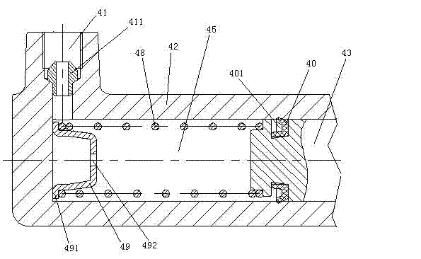
[0052] The booster regulator 4 includes a cylinder 42, a piston 43 and a cam 44 matched with the cylinder. The cam 44 is an eccentric wheel. The piston 43 and the cylinder 42 form a variable volume space 45, and the boost regulator port 41 is used to communicate the variable volume space 45 with the outer space of the cylinder 42. A piston rod 46 is provided on the piston 43. The cross section of the piston rod 46 is smaller than the cross section of the piston 43, and the piston rod 46 and the piston 43 are welded together. A support ring 421 is provided on the right end of the cylinder 42. The support ring 421 is connected to the cylinder 42 by bolts. The diameter of the inner hole of the support ring 421 is the same as the diameter of the piston rod 46. The right end of the piston rod 46 penetrates the right end of the cylinder 42 and is hinged to the left end of the c...
Embodiment 3
[0055] Example three, see Figure 8 The difference in mechanical structure from the second embodiment is that the connecting rod 10 includes a piston rod connector 105, a double-ended screw 103 and a cam connector 104. The piston rod connector 105 and the cam connector 104 are respectively provided with The threaded holes matched with the double-headed screw, both ends of the double-headed screw 103 are threadedly connected to the threaded hole of the piston rod connector 105 and the threaded hole of the cam connector 104, and the ring 101 is arranged on the cam connector 104. The ring 101 and the cam connector 104 are an integral structure. The length of the connecting rod 10 is changed by changing the depth of the double-headed screw 103 screwed into the piston rod connector 105 or the cam connector 104 to realize the change of the starting and ending positions of the piston in the cylinder 42.
PUM
 Abstract
Description
Claims
Application Information
 - R&D
- Intellectual Property
- Life Sciences
- Materials
- Tech Scout
- Unparalleled Data Quality
- Higher Quality Content
- 60% Fewer Hallucinations
Browse by: Latest US Patents, China's latest patents, Technical Efficacy Thesaurus, Application Domain, Technology Topic, Popular Technical Reports.
© 2025 PatSnap. All rights reserved.Legal|Privacy policy|Modern Slavery Act Transparency Statement|Sitemap|About US| Contact US: help@patsnap.com


