Method for measuring stain on optical lens

An optical lens, lens technology, used in optical testing flaws/defects, scattering characteristics measurement, etc.

Inactive Publication Date: 2012-05-09
HEFEI INSTITUTES OF PHYSICAL SCIENCE - CHINESE ACAD OF SCI
View PDF4 Cites 29 Cited by
  • Summary
  • Abstract
  • Description
  • Claims
  • Application Information

AI Technical Summary

Problems solved by technology

[0003] The problem solved by the present invention is: an optical lens pollution measuring device, which can judge whether the optical instrument lens is polluted b...

Method used


Image

  • Method for measuring stain on optical lens
  • Method for measuring stain on optical lens
  • Method for measuring stain on optical lens

Examples


Embodiment Construction

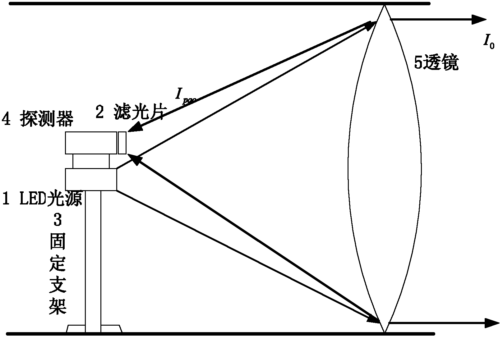
[0059] like figure 1 As shown, the backscattered light signal detection part of the present invention includes: LED light source 1, optical filter 2, fixed bracket 3, detector 4, LED is installed at the center behind the lens inside the instrument, and the direction of light is directed to the lens; the detector adopts The PIN photodiode is fixed at the center of the rear of the measured lens through a fixed bracket, and is located next to the light source, and the detector surface source points to the lens surface. The optical filter is fixed at the front end of the detector area source to filter out the influence of stray light.

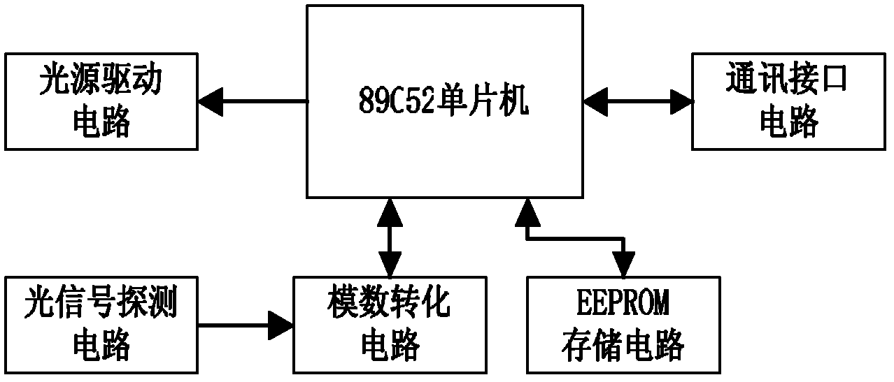
[0060] like image 3 As shown, the measurement control circuit of the present invention comprises: a light source drive circuit, a preamplifier circuit, a filter circuit, a signal demodulation circuit, an analog-to-digital conversion circuit, a single-chip microcomputer, an output interface circuit, and a memory circuit. in:

[0061] The LED lig...


PUM


Abstract

The invention relates to a method for measuring stain on optical lens, a photoelectric signal detection part is composed of an infrared LED light source, a detector, an optical filter and an installation support. The infrared LED light source is arranged at the rear part of the lens to be detected in an optical device through a fixed support, the emission direction points at the lens; the detector is fixed at the rear part of the lens to be detected through the fixed support; the optical filter is pasted at the front end of the non-point source of the detector, so that the interference of stray light can be removed; a measure control circuit comprises a one-chip microcomputer, a light source drive circuit, a preposed amplification circuit, a filter circuit, a signal demodulation circuit, an analog to digital conversion circuit, a data output circuit and a memory circuit. The backscattering signals received by the detector are subjected to circuit amplification and treatment, the central processor determines the pollution extent on the lens face, and when the lens surface pollution extent exceeds early warning threshold value, the alarm signal is output to alert the requirement forcleaning the lens. The method for measuring stain on optical lens is used for monitoring lens surface pollution extent with outfield on-line operation, and provides the guarantee for normal operationof system.

Description

technical field [0001] The invention relates to the application field of optical instruments, and is a device for automatically monitoring surface pollution of optical lenses based on light backscattering theory, and is suitable for lens pollution measurement of optical instruments operating on-line in an external field. Background technique [0002] At present, many optical instruments are installed and used in the field for online measurement in fields such as meteorology, environmental protection, ecological flux, and optical communication. The ensuing problem is: because the optical lens is exposed to the external field, it will be polluted by dust or other pollutants, the cleanliness of the lens mirror will decrease, and the transmittance will decrease, resulting in weakened received or emitted light intensity, which will affect the measurement. As a result, in severe cases, the instrument may not work properly. At present, there is no effective method to automatically...

Claims


Application Information

Patent Timeline
IPC IPC(8): G01N21/94G01N21/49
Inventor 程寅刘文清刘建国陆亦怀桂华侨王亚平陈军
Owner HEFEI INSTITUTES OF PHYSICAL SCIENCE - CHINESE ACAD OF SCI
Why Eureka
Try Eureka