LCD (liquid crystal display) driving device and driving method

A liquid crystal display and driving device technology, applied to static indicators, instruments, etc., can solve the problems of complex wiring, large number of wiring, and high production cost

Active Publication Date: 2012-05-09
BOE TECH GRP CO LTD +1
View PDF5 Cites 28 Cited by
  • Summary
  • Abstract
  • Description
  • Claims
  • Application Information

AI Technical Summary

Problems solved by technology

[0004] The inventors found that the driving device of the liquid crystal display provided by the prior art has at least the following problems: since one output channel corresponds to driving one data line or gate line, when the number of output channels of the data driver IC and the gate driver IC is constant, , more data driver ICs and gate driver ICs need to be installed, the number of traces on the PCB is large, and the wiring is complicated, so the production cost is high

Method used


Image

  • LCD (liquid crystal display) driving device and driving method
  • LCD (liquid crystal display) driving device and driving method
  • LCD (liquid crystal display) driving device and driving method

Examples


Embodiment 1

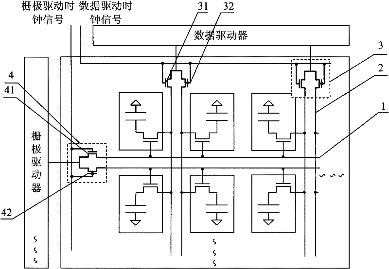
[0062] In this embodiment, the scheme of setting up an array of gate line driving modules and an array of data line driving modules is adopted, and further, the two gate lines connected to the gate line driving module are one odd-numbered row gate line and one even-numbered row Row gate lines; the two data lines connected to the data line driving module are an odd-numbered column data line and an even-numbered column data line.

[0063] Specifically, the gate line driving module 4 used includes: a high-level active first thin film transistor 41 and a low-level active second thin film transistor 42, wherein the gate of the first thin film transistor 41 and the data line drive clock signal The output terminal of the second thin film transistor 42 is connected to an output channel of the gate driver, and its drain is connected to an odd-numbered gate line 1; the gate of the second thin film transistor 42 is connected to the gate line drive clock signal connected to the output ter...

Embodiment 2

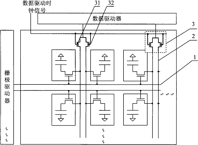
[0075] In this embodiment, only the array of data line driving modules is adopted, and further, the two data lines connected to the data line driving modules are one odd-numbered column data line and one even-numbered column data line.

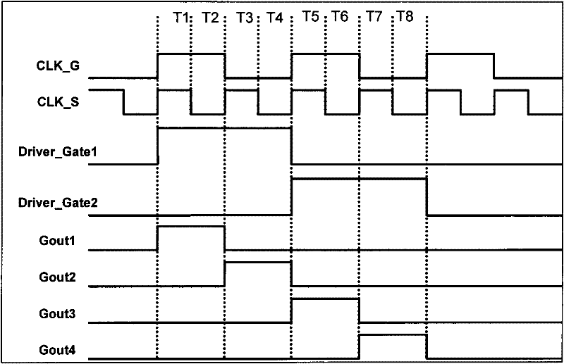
[0076] Specifically, such as Figure 4 As shown, it is the driving timing diagram of Embodiment 2 of the present invention, wherein CLK-S represents the data line driving clock signal, Driver-Gate1 represents the output of the first output channel of the gate drive IC, and Driver-Gate2 represents the gate drive IC The output of the second output channel, Gout1 represents the output of the first row of gate lines, Gout2 represents the output of the second row of gate lines, Gout3 represents the output of the third row of gate lines, and Gout4 represents the output of the fourth row of gate lines.

[0077] Specifically, such as image 3 and Figure 4as shown,

[0078] 1) During the T1 and T2 periods, the first output channel Driver_Date1 of t...

Embodiment 3

[0083] In this embodiment, only the gate line driving module array is adopted, and further, the two gate lines connected to the gate line driving module are one odd-numbered row gate line and one even-numbered row gate line.

[0084] Specifically, such as Figure 6 As shown, it is the driving timing diagram of Embodiment 3 of the present invention, wherein CLK-G represents the gate line drive clock signal, Driver-Gate1 represents the output of the first output channel of the gate drive IC, and Gout1 represents the gate line of the first row Output, Gout2 represents the output of the gate line of the second row, Gout3 represents the output of the gate line of the third row, and Gout4 represents the output of the gate line of the fourth row.

[0085] Specifically, such as Figure 5 and Figure 6 As shown, when the first output channel Driver_Date1 of the gate driver IC outputs a high level:

[0086] 1) During the T1 time period, CLK_G is at a high level, the first thin film t...


PUM


Abstract

The embodiment of the invention discloses an LCD (liquid crystal display) driving device and driving method, relating to the field of LCDs and capable of reducing the numbers of gate drive integrated circuits (ICs) and data drive ICs. The driving device comprises a gate driver and a data driver, a gate line drive module array and / or a data line drive module array, wherein the gate line drive module array consists of A gate line drive modules, each gate line drive module is connected with one output channel of the gate driver and is connected with two gate lines, and the gate line drive modules are used for driving the gate lines connected to the gate line drive modules to start successively, where A is larger than or equal to 1 and smaller than or equal to M / 2, and M is the total number of gate line rows; and the data line drive module array consists of B data line drive modules, each data line drive module is connected with one output channel of the data driver and is connected with two data lines, and the data line drive modules are used for driving the data lines connected to the data line drive modules to start successively, where B is larger than or equal to 1 and smaller than or equal to N / 2, and N is the total number of data line columns.

Description

technical field [0001] The invention relates to the field of liquid crystal displays, in particular to a driving device and a driving method of a liquid crystal display. Background technique [0002] Liquid Crystal Display (LCD) has the characteristics of small size, low power consumption, and no radiation, and has now occupied a dominant position in the field of flat panel display. [0003] The main structure of the liquid crystal display includes an array substrate and a color filter substrate that are boxed together and the liquid crystal is sandwiched between them. On the array substrate, gate lines that provide scanning signals, data lines that provide data signals, pixel electrodes that form pixel points, and A common electrode line that provides a common voltage, a black matrix and a colored resin are formed on the color filter substrate, wherein the gate lines are driven by a gate driver, and the gate driver is composed of several gate drive integrated circuits (Inte...

Claims


Application Information

Patent Timeline
Patent Type & Authority Applications(China)
IPC IPC(8): G09G3/36
CPCG09G2310/0297G09G3/3677G09G3/3688G09G2300/0426G09G2300/0408G09G2310/08
Inventor 时哲
Owner BOE TECH GRP CO LTD
Why Eureka
Try Eureka