Photovoltaic array maximum power point tracking servo system and control method

A maximum power point, photovoltaic array technology, applied in photovoltaic modules, photovoltaic power generation, photovoltaic power stations, etc., can solve the problems of cumulative error, slow system action, poor reliability, etc., to increase the maximum output power, increase the received radiant energy, and eliminate the The effect of accumulating errors

Inactive Publication Date: 2012-05-09
SHANGHAI YUEJIA ENERGY TECH
View PDF0 Cites 22 Cited by
  • Summary
  • Abstract
  • Description
  • Claims
  • Application Information

AI Technical Summary

Problems solved by technology

The power generation of the system cannot be maximized
[0005]Second, the follow-up system mostly uses a single-axis follow-up system, and the tracking efficiency is low
[0006]Third, the existing servo system does not compare and check the solar radiation and ambient brightness, and the accuracy and reliability of the automatic servo system are low , prone to accumulative errors due to seasonal changes
[0008]The idea of ​​passive tracking control is simple, and the design of the controller is easy, but the general photosensitive sensor has a wide photosensitive angle. Not sensitive to light angle deviation
In addition, the follow-up system is installed outdoors, and the photosensitive element is often covered by dust, which will weaken the light-sensing ability of the photosensitive element, cause the system to move slowly, and the deviation angle of the initial tracking will become larger or when the two photosensitive elements are polluted to different degrees , their output will form an inherent bias, which will cause the solar panels to be unable to accurately track the sun's position

Method used


Image

  • Photovoltaic array maximum power point tracking servo system and control method
  • Photovoltaic array maximum power point tracking servo system and control method
  • Photovoltaic array maximum power point tracking servo system and control method

Examples


Embodiment Construction

[0032] The present invention will be described in detail below in conjunction with the accompanying drawings.

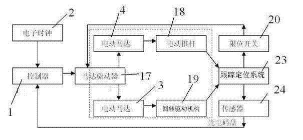
[0033] figure 1 It is a structural block diagram of the photovoltaic array maximum power point tracking servo system of the present invention.

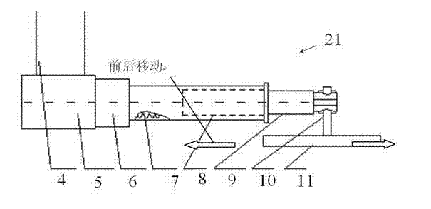
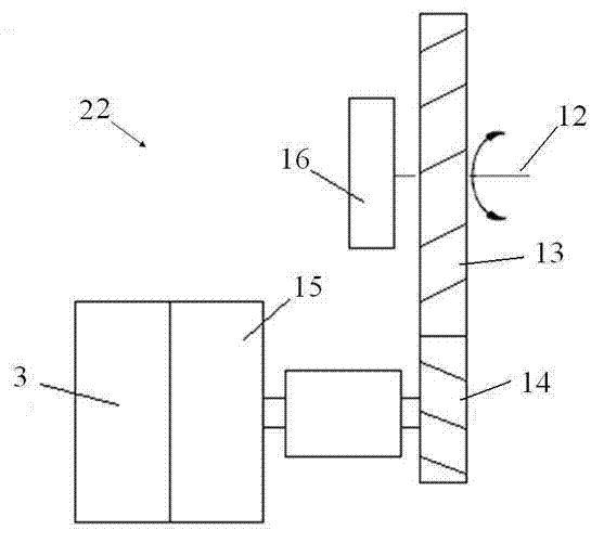
[0034] As shown in the figure, the photovoltaic array maximum power point tracking servo system disclosed by the present invention includes a clock circuit connected to a single-chip microcomputer control system, a two-axis mechanical tracking positioning system 23, and a photoelectric detection device, wherein the two-axis mechanical tracking The positioning system 23 includes a first tracking part 21 and a second tracking part 22 connected to the battery board support 16, the battery board and the photoelectric detection device are arranged on the battery board support 16, and the single-chip control system (for example, PLC or MCU controller 1 ) to respectively control and drive the first tracking component 21 and the se...


PUM


Abstract

The invention discloses a photovoltaic array maximum power point tracking servo system comprising a clock circuit, a double-shaft mechanical tracking and locating system and a photovoltaic detecting device respectively connected with a singlechip control system. The double-shaft mechanical tracking and locating system comprises a first tracking component and a second tracking component connected with a battery panel bracket. A battery panel and the photovoltaic detecting device are provided on the battery panel bracket. The singlechip control system respectively controls and drives the first tracking component and the second tracking component to drive the battery panel and the photovoltaic detecting device to move in the vertical direction and the horizontal direction. The driving system adopted by the invention is a double-shaft active solar servo system which can realize the sun tracking under all weather conditions, has high precision, can always align the solar battery panel to the sun and maintain the maximum generating efficiency. Furthermore, the invention also discloses a control method of the system.

Description

technical field [0001] The invention belongs to a photovoltaic control system, and relates to a photovoltaic system maximum power point tracking control technology and method. Background technique [0002] Photovoltaic power generation is a clean and non-polluting renewable energy with broad prospects for development. Photovoltaic power generation has become the fastest growing technology in the world. However, it also has the problems of intermittency, light direction and intensity changing with time, which puts forward higher requirements for the collection and utilization of solar energy. At present, many photovoltaic panel arrays are basically fixed. The photovoltaic power generation system without a servo system has the disadvantage of not being able to keep the sunlight perpendicular to the panel. Its maximum power tracking (MPPT) is only realized by pure algorithm control. Photovoltaic power generation is greatly affected by natural conditions and sunshine, and solar...

Claims


Application Information

Patent Timeline
Patent Type & Authority Applications(China)
IPC IPC(8): H02N6/00G05D3/12G05F1/67H02P5/74H02S10/00
CPCY02E10/58Y02E10/56
Inventor 杨建中
Owner SHANGHAI YUEJIA ENERGY TECH
Why Eureka
Try Eureka