Control channel transmission method and device

A technology for a control channel and a transmission method, applied in the field of transmission methods and devices for control channels, can solve problems such as power reduction, interference reduction, and limited coverage, and achieve the effects of improving resource utilization efficiency, improving coverage distance, and improving receiving performance

Active Publication Date: 2012-05-09
江苏华木空间结构有限公司
View PDF4 Cites 15 Cited by
  • Summary
  • Abstract
  • Description
  • Claims
  • Application Information

AI Technical Summary

Problems solved by technology

At present, for the convenience of the algorithm, in the OFDM multi-carrier system, for the power of the downlink control channel, the eNB allocates equal power to the PDCCH of each UE, that is, removes (Physical Control Format Indication Channel, PCFICH) and (Physical HARQ Indication Channel, In addition to the power occupied by PHICH), the remaining power is equally distributed to each CCE or REG occupied by PDCCH, and the appropriate DCI format and aggregation level are selected according to the length of the UE's DCI information and channel conditions. The problem with this method is that it cannot solve the problem of co-frequency interference problem
In addition, there is also a method to adjust the PDCCH transmission power according to the UE’s received signal-to-noise ratio feedback, but it still cannot solve the contradiction between the overall interference intensity between cells and the overall coverage level, because increasing the power can enhance the UE coverage, but the interference increases ; Reduced power, reduced interference, but limited coverage
[0007] Therefore, in the existing technology, there is no method for improving the coverage distance of the PDCCH channel in the presence of inter-cell interference

Method used


Image

  • Control channel transmission method and device
  • Control channel transmission method and device
  • Control channel transmission method and device

Examples


Embodiment 1

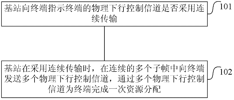
[0070] figure 2 Shown is the common transmission method of PDCCH in the mobile communication network, that is: each PDSCH is indicated by a PDCCH in the same subframe, the terminal first detects the PDCCH, and determines the relevant information of receiving the PDSCH according to the control information in the PDCCH. figure 2 Shown in , the aggregation level of the PDSCH is 4, that is, 4 CCEs are occupied.

[0071] In the above existing method, for some terminals with poor channel quality, the solution adopted by the base station can only be to use a larger aggregation level, for example, use 8 CCEs to improve the detection success rate.

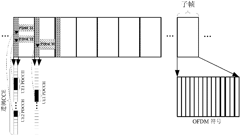
[0072] image 3 It is a schematic diagram of continuous transmission of PDCCH in this embodiment, image 3 In order to implement a PDSCH transmission for a terminal with poor channel quality, the base station sends three PDCCHs in three consecutive subframes. These three PDCCHs can be different HARQ versions of the same information. Aft...

example 2

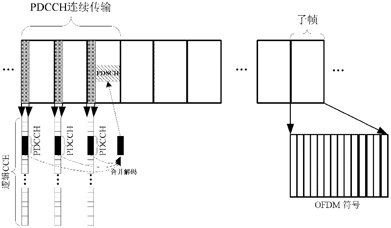
[0077] Figure 4 Example 2 of continuous transmission of PDCCH in this embodiment;

[0078] In the scheme of PDCCH continuous transmission, the number or times of PDCCH continuous transmission needs to be determined, including the following schemes:

[0079] (1) It can be a certain number, for example, preferably 3 times, as long as the base station uses the PDCCH continuous transmission scheme for a certain terminal, it will transmit continuously 3 times fixedly. image 3 Shown in is a fixed continuous transfer of 3 times.

[0080] (2) It can be configured by the base station, for example, configured with 1-2 bits. Taking 2 bits as an example, it corresponds to four consecutive transmission times 1, 2, 3 and 4.

[0081] Figure 4 In order to implement a PDSCH transmission for a terminal with poor channel quality, the base station sends 4 PDCCHs in 4 consecutive subframes. These 4 PDCCHs can be different HARQ versions of the same information, and the terminal receives 4 PD...

Embodiment 3

[0085] Figure 5 Example 3 of continuous transmission of PDCCH in this embodiment;

[0086] In this example, with image 3 and Figure 4 The difference between the continuous transmissions is that the base station can set different consecutive transmission times for different terminals.

[0087] Both terminal 1 and terminal 2 are located at the edge of the network, and the channel quality is not good, but the channel quality of terminal 1 is better than that of terminal 2, so terminal 1 does not need to use an excessively high aggregation level, for example, aggregation level 4 Instead of using 8, on the other hand, there is no need for too many consecutive transmission times, for example, 3 consecutive transmissions instead of 4; on the one hand, terminal 2 needs to use the highest aggregation level, for example, using aggregation level 8, and on the other hand, perform The maximum number of consecutive transmissions, for example, 4 consecutive transmissions.

[0088] It ...


PUM


Abstract

The invention discloses a control channel transmission method and device comprising: a base station indicates to a terminal whether a physical downlink control channel of the terminal adopts serial transmission, when the serial transmission is adopted, sends multiple physical downlink control channels to the terminal in continuous multiple sub-frames and completes one resource distribution to the terminal via the multiple physical downlink control channels. The control channel transmission method of the invention can make UE obtain time selectivity gain and coding combination gain by adopting the serial transmission, can improve flexible degree of PDCCH resource occupation and can raise the resource utilization rate to improve the covering distance of PDCCH in order to enhance receiving property of PDCCH.

Description

technical field [0001] The present invention relates to the communication field, in particular to a control channel transmission method and device. Background technique [0002] With the rapid development of wireless communication technology, limited spectrum resources have gradually become the main factor restricting the development of wireless communication, but it is the limited spectrum resources that stimulate the emergence of new technologies. Capacity and coverage are two important performance indicators in a wireless communication system. In order to increase capacity, co-frequency networking is often used. However, co-frequency networking increases inter-cell interference, resulting in reduced coverage performance. [0003] In the Long Term Evolution (LTE) system, the Orthogonal Frequency Division Multiple Access (OFDMA) technology is used in the downlink, which can significantly reduce the interference in the cell. In the high-frequency network, the inter-cell int...

Claims


Application Information

Patent Timeline
Patent Type & Authority Applications(China)
IPC IPC(8): H04L1/00H04L1/06H04W72/04
CPCH04W72/12
Inventor 关艳峰陈宪明左志松李永
Owner 江苏华木空间结构有限公司
Why Eureka
Try Eureka