Eureka AIR delivers breakthrough ideas for toughest innovation challenges, trusted by R&D personnel around the world.

Jib system and telescopic oil cylinder thereof

A telescopic oil cylinder and boom technology, applied in the direction of fluid pressure actuating devices, can solve the problems of increasing the size of the hydraulic oil cylinder, difficult to meet the requirements of use, and increasing the telescopic load, so as to reduce the difficulty of processing and assembly, and improve the economy. Applicability, effect of size reduction

Active Publication Date: 2012-05-16
XCMG FIRE FIGHTING SAFETY EQUIP CO LTD
View PDF13 Cites 1 Cited by
  • Summary
  • Abstract
  • Description
  • Claims
  • Application Information

AI Technical Summary

Problems solved by technology

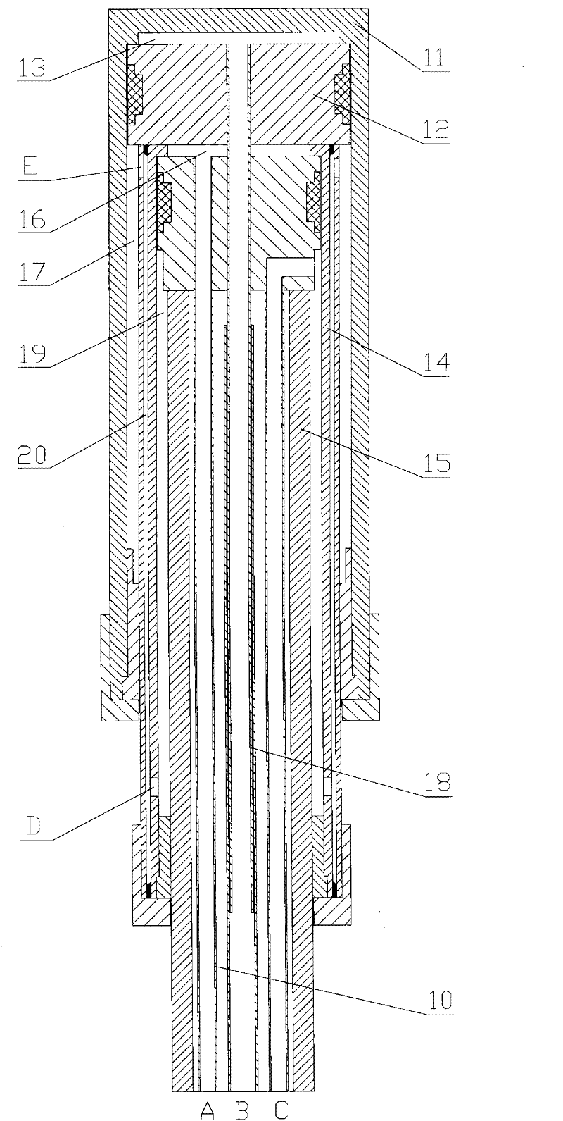
[0006] This kind of oil cylinder has a complex structure, and there are two points that require high processing technology
Among them, since there is an oil passage 20 in the primary piston rod 14, the oil passage 20 can be processed with a deep hole drill, but the disadvantage is that the straightness of the drilling is very high, and the wall thickness of the general cylinder rod is relatively small, so it is difficult to ensure a straight line. In addition, the length of the drill bit is limited, and it is difficult to process long oil cylinders; the oil passage 20 can also be welded with two-stage sleeves, leaving a certain gap in the middle. Although this method can process long oil cylinders, it will affect the strength and stability of the cylinder rod. , while cleaning the middle cavity is more difficult
Moreover, in order to ensure that the hydraulic oil can be delivered to the rodless cavity 13, the second core tube 18 needs to adopt a two-stage nesting form, which requires very high straightness and coaxiality. There is a seal for sealing, which requires very strict processing and welding of the core tube, and problems such as core tube bending and oil leakage are prone to occur in the later stage
The telescopic oil cylinders of high-lift vehicles are generally very long, with a stroke of about 10 meters, so the above two points are difficult to meet the use requirements. Even if they are barely achieved, it will be difficult to quantitatively produce due to the complicated process
[0007] At the same time, because the structure of this oil cylinder is too complicated, the later failure rate will be very high, and because there are many failure points, once a problem occurs, it will be difficult to judge the specific cause of the failure, which will seriously affect the production progress and quality stability of the main engine product; and In order to ensure that its complex internal structure can be realized while satisfying the performance, the external dimensions of the oil cylinder must be relatively increased, resulting in an increase in the corresponding structural size and weight. However, once the telescopic load of the boom is too large, in order to ensure that the hydraulic system can provide the maximum If the hydraulic cylinder can output enough thrust, it is necessary to increase the size of the hydraulic cylinder, and the increase in the size of the cylinder will make it difficult to arrange the internal space of the boom structure, so it is necessary to increase the size of the boom, which in turn increases the weight of the boom At the same time, the weight of the telescopic cylinder itself will also increase, which will further increase the telescopic load, which will form a vicious circle and cause the product to fail to meet the design standards
[0008] Moreover, because the existing boom telescopic oil cylinder is a double-acting oil cylinder, it needs high-pressure oil in the rod cavity to retract when retracting, but because the area ratio of the rodless cavity to the rod cavity is generally very large, it leads to When the oil cylinder is retracted, the pressure of the hydraulic system is too high, which cannot meet the use of existing products

Method used


Image

  • Jib system and telescopic oil cylinder thereof
  • Jib system and telescopic oil cylinder thereof
  • Jib system and telescopic oil cylinder thereof

Examples


Embodiment Construction

[0032] The core of the present invention is to provide a telescopic oil cylinder for the boom system of engineering vehicles, which has simple structure, good maintainability and high reliability. Another core of the present invention is to provide a boom system including the above-mentioned telescopic oil cylinder, which can meet the market demand for large-scale engineering machinery.

[0033]The orientation words such as upper and lower involved in this article are defined based on the position of the telescopic cylinder when the boom system is in working condition; at the same time, the orientation words such as inner and outer mentioned in this article are based on the The central axis of is defined by the datum, the position close to the central axis is inside, and the position away from the central axis is outside. It should be understood that the orientation words used herein shall not limit the protection scope of this patent.

[0034] In order to enable those skille...


PUM


Abstract

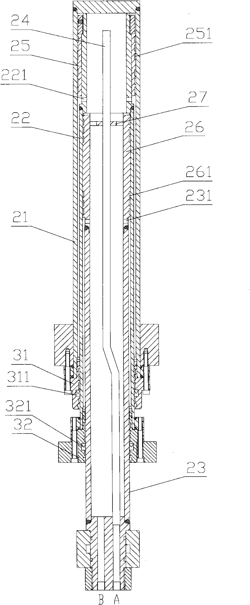
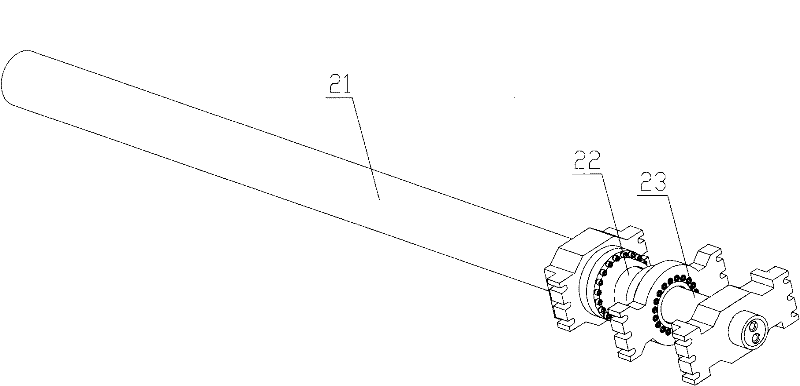
The invention discloses a jib system and a telescopic oil cylinder thereof. The disclosed jib system comprises a cylinder jacket (21), a first piston rod (22), a second piston rod (23) and a core pipe (24) for conveying hydraulic oil into the telescopic oil cylinder. The cylinder jacket (21) comprises a first chamber which is sleeved on the first piston rod (22); the first piston rod (22) comprises a second chamber which is sleeved on the second piston rod (23); the second piston rod (23) comprises a third chamber which is sleeved on the core pipe (24); the first piston rod (22) further comprises a first channel (221) which is communicated with the first chamber and the third chamber; and the second piston rod (23) further comprises a second channel (231) which is communicated with the second chamber and the third chamber. The telescopic oil cylinder is simple in structure, and is easy to process; the assembling difficulty and the production cost of the oil cylinder are lowered effectively; convenience of the engineering design is provided; and the economical applicability of engineering vehicles with the jib system is improved.

Description

technical field [0001] The invention relates to the field of engineering vehicles, in particular to a telescopic oil cylinder used for an engineering vehicle boom system. In addition, the present invention also relates to a boom system comprising the above-mentioned telescopic oil cylinder. Background technique [0002] The telescopic function of the boom of engineering vehicles such as telescopic box-arm fire trucks and aerial work vehicles can only be realized through the promotion of hydraulic cylinders. [0003] Please refer to figure 1 , figure 1 It is a schematic cross-sectional view of a typical boom telescopic oil cylinder in the prior art. [0004] In the current boom system, the telescopic cylinders used are mostly double-acting cylinders, and their working process is described as follows: [0005] When the oil cylinder needs to be extended, the oil is fed through the oil port B and the oil port C, wherein the oil inlet of the oil port B passes through the firs...

Claims


Application Information

Patent Timeline
IPC IPC(8): F15B15/16F15B15/20
Inventor 史先信李丛南田志坚孔德美
Owner XCMG FIRE FIGHTING SAFETY EQUIP CO LTD
Why Eureka
Eureka Blog
Learn More