Electric power transmisison system and antenna

A power transmission and antenna technology, applied in electromagnetic wave systems, electric traction, transportation and packaging, etc., can solve problems such as preventing effective power transmission, reducing antenna characteristics, and unable to perform effective power transmission, and achieving effective power transmission and stable antenna characteristics. Effect

Inactive Publication Date: 2012-05-16
EQUOS RES
View PDF5 Cites 28 Cited by
  • Summary
  • Abstract
  • Description
  • Claims
  • Application Information

AI Technical Summary

Problems solved by technology

However, according to the above-described structure, in some cases, the assumed antenna characteristics cannot be obtained due to variations in the inductance component of the electric node having an indeterminate shape, and as a result, efficient power transmission cannot be performed.
In addition, the electric node has a resistive component, and because of the resistive component, the characteristics of the antenna as a whole can be degraded, which also prevents efficient power transmission

Method used


Image

  • Electric power transmisison system and antenna
  • Electric power transmisison system and antenna
  • Electric power transmisison system and antenna

Examples


Embodiment Construction

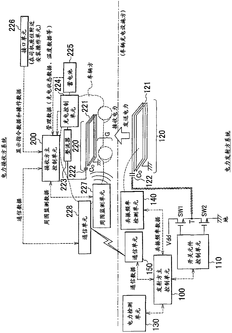
[0057] Embodiments of the present invention will be described below with reference to the accompanying drawings. figure 1 is a diagram showing an example in which a power transmission system according to an embodiment of the present invention is applied to a vehicle charging facility. The power transmission system according to the embodiment of the present invention is suitable for use in, for example, a system for charging vehicles such as electric vehicles (EV) and hybrid electric vehicles (HEV). Then, use figure 1 An example of application to a vehicle charging facility shown in is described below. Note that the power transmission system according to the embodiment of the present invention can also be used in power transmission of systems other than vehicle charging facilities.

[0058] exist figure 1 In , the configuration shown under the alternate long and short dashed lines is the transmitter system, and is the vehicle charging facility in this example. On the oth...


PUM


Abstract

An electric power transmission system includes: a transmitting-side system that includes switching elements (SW1 and SW2) that convert a direct-current voltage to an alternating-current voltage and that output the alternating-current voltage and a transmitting-side magnetic resonance antenna unit (120) that has a first inductor (121) and a first capacitor (122) directly coupled to each other and to which the output alternating-current voltage is input; and a receiving-side system that includes a second inductor (221) and a second capacitor (222) directly coupled to each other and that resonates with the transmitting-side magnetic resonance antenna unit (120) via electromagnetic field to thereby receive electric energy output from the transmitting-side magnetic resonance antenna unit (120).

Description

technical field [0001] The present invention relates to a wireless power transmission system and an antenna using a magnetic resonance antenna according to a magnetic resonance method. Background technique [0002] In recent years, a technique of wirelessly transmitting electric power (electric energy) without using a power supply cable or the like has been vigorously developed. Among various types of methods for wirelessly transmitting electric power, there is a technique called a magnetic resonance method, which has received much attention. A research group at MIT proposed a magnetic resonance method in 2007, and related techniques are described in, for example, a Japanese translation of the publication of PCT Application No. 2009-501510 (JP-A-2009-501510). [0003] In the magnetic resonance wireless power transfer system, the resonance frequency of the transmitting side magnetic resonance antenna and the resonance frequency of the receiving side magnetic resonance antenn...

Claims


Application Information

Patent Timeline
Patent Type & Authority Applications(China)
IPC IPC(8): H02J17/00H01Q1/38
CPCH02J5/005Y02T90/125Y02T10/7044Y02T10/7005Y02T90/14Y02T10/7241B60L2210/40Y02T90/127H01F38/14B60L2240/547Y02T90/122B60L2240/549B60L2240/545Y02T10/7088B60L11/1833Y02T90/12B60L2250/16Y02T10/705B60L2210/30B60L11/1861B60L11/182Y02T10/7072B60L53/36B60L58/12B60L53/124B60L53/126H02J7/00034Y02T10/70Y02T10/72H02J50/12H02J50/80H02J50/70
Inventor 山川博幸伊藤泰雄牛来直树宫城慧菅原隆下川茂则
Owner EQUOS RES
Why Eureka
Try Eureka