Method for producing a plasma jet and plasma source

A plasma source and plasma technology, applied in the direction of plasma, discharge tube, electrical components, etc., can solve the problems of unsuitable size, high cost, and complex structure of plasma processing devices

Inactive Publication Date: 2012-05-16
LEYBOLD OPTICS
View PDF14 Cites 2 Cited by
  • Summary
  • Abstract
  • Description
  • Claims
  • Application Information

AI Technical Summary

Problems solved by technology

[0007] Known inductively and / or capacitively excited high-frequency plasma sources are cost-intensive solutions, require a lot of space due to the use of the mentioned magnetic field coils and have complex constructions, making them suitable for large-area substrates, such as rectangular The size of the plasma treatment unit of the source is not suitable for use in architectural glass coating plants or drum plants (Trommelanlage)

Method used


Image

  • Method for producing a plasma jet and plasma source
  • Method for producing a plasma jet and plasma source
  • Method for producing a plasma jet and plasma source

Examples


Embodiment Construction

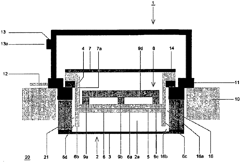
[0059] Figure 1a The schematic diagram shows a cross section of a high-frequency plasma source 1 installed in a vacuum chamber 10 according to the present invention. The high-frequency plasma source 1 has a plasma container 2, an extraction electrode 3 and a high-frequency electrode device 4. The process gas and reaction gas, such as argon and oxygen, can be introduced into the plasma container 2 through the gas input device 12.

[0060] The plasma container 2 has a front surface and a back surface, and the plasma chamber 2a is located between them. In addition, the plasma container 2 has side walls 16, which extend into the interior 20 of the vacuum chamber 10 and are provided with extraction electrodes 3 constituting the front surface of the plasma container 2 on their end surfaces. These electrodes are thus opposed to the interior of the vacuum chamber. 20 permeable defines the plasma chamber 2a. The lead electrode 2 can also be constructed in a curved manner.

[0061] The pl...


PUM


Abstract

In the method for producing a plasma jet, which is extracted from a plasma produced by electric and magnetic fields by a high frequency voltage being applied to an extraction electrode and an HF electrode apparatus having an excitation electrode with an excitation surface, a plasma chamber being arranged between an extraction electrode and an excitation surface and, as compared with the extraction electrode, the time average of the plasma lying at a higher potential accelerating positive plasma ions, and the plasma and extracted plasma jet being influenced by a magnetic field, the invention provides that, in order to produce a magnetic field, use is made of a planar magnetron which is arranged after the excitation electrode on the side facing away from the plasma, and the magnetic north poles and magnetic south poles of which are directed into the interior of the plasma chamber, so that a curved magnetic field projecting into the interior of the plasma chamber is formed. In the plasma source for carrying out the method, having a plasma vessel with an extraction electrode and having an HF electrode apparatus, having an excitation electrode with an excitation surface, which is or can be connected via a matching network to an HF generator, a plasma chamber, in which a plasma can be excited, being located between excitation surface and extraction electrode, and the size of the area of the extraction electrode and of the excitation surface being chosen such that virtually all of the high frequency voltage is dropped across the extraction electrode; having a magnetic device for reducing the magnetic field, provision is made for the magnetic device to have at least one magnetic north pole and one magnetic south pole, which are in each case arranged after the excitation electrode on the side facing away from the plasma chamber and are directed into the interior of the plasma chamber, so that a curved magnetic field projecting into the interior of the plasma chamber can be formed, wherein at least one of the north or south poles is designed to be elongated, so that a tunnel-like region can be formed in which charged particles can be retained and along which they are able to propagate.

Description

Technical field [0001] The invention relates to a method for generating a plasma jet and a plasma source for implementing the method according to the features of the preambles of the independent claims, respectively. Background technique [0002] A plasma source excited with a high frequency (HF) in the frequency range between 1 MHz and 20 MHz and a plasma chamber closed by a grid from which a plasma beam is drawn are known, in which the plasma is usually applied by a magnetic field There is a difference between body perceptual and capacitive stimulation. A modified Helmholtz coil is used in this type of inductive and inductive / capacitive mixed excited high-frequency plasma source, which generates a substantially uniform field perpendicular to the inductive high-frequency coupling coil or turns and This leads to an increase in plasma concentration. [0003] DE 694 210 33T2 discloses, for example, an inductive plasma source operating in the radio frequency range (RF), where the pl...

Claims


Application Information

Patent Timeline
Patent Type & Authority Applications(China)
IPC IPC(8): H01J37/32
CPCH01J37/3266H01J37/32357
Inventor M·舍雷尔J·皮斯特纳
Owner LEYBOLD OPTICS
Why Eureka
Try Eureka