Motor driving device

A driving device and motor technology, which is applied in the direction of controlling electromechanical transmission device, suppressing motor vibration control, motor generator control, etc. Effect

Active Publication Date: 2012-05-23
YASKAWA DENKI KK
View PDF5 Cites 8 Cited by
  • Summary
  • Abstract
  • Description
  • Claims
  • Application Information

AI Technical Summary

Problems solved by technology

In addition, there is also a problem that, when the PWM control method of the power conversion device is a two-phase modulation method, an excessive resonant current may flow including the instantaneous magnetic saturation of the common mode choke coil at the time of switching between two-phase modulation. large filter current

Method used


Image

  • Motor driving device
  • Motor driving device
  • Motor driving device

Examples


Embodiment 1

[0033] First, use Figure 8 , 9 , 10 to illustrate the existing motor drive.

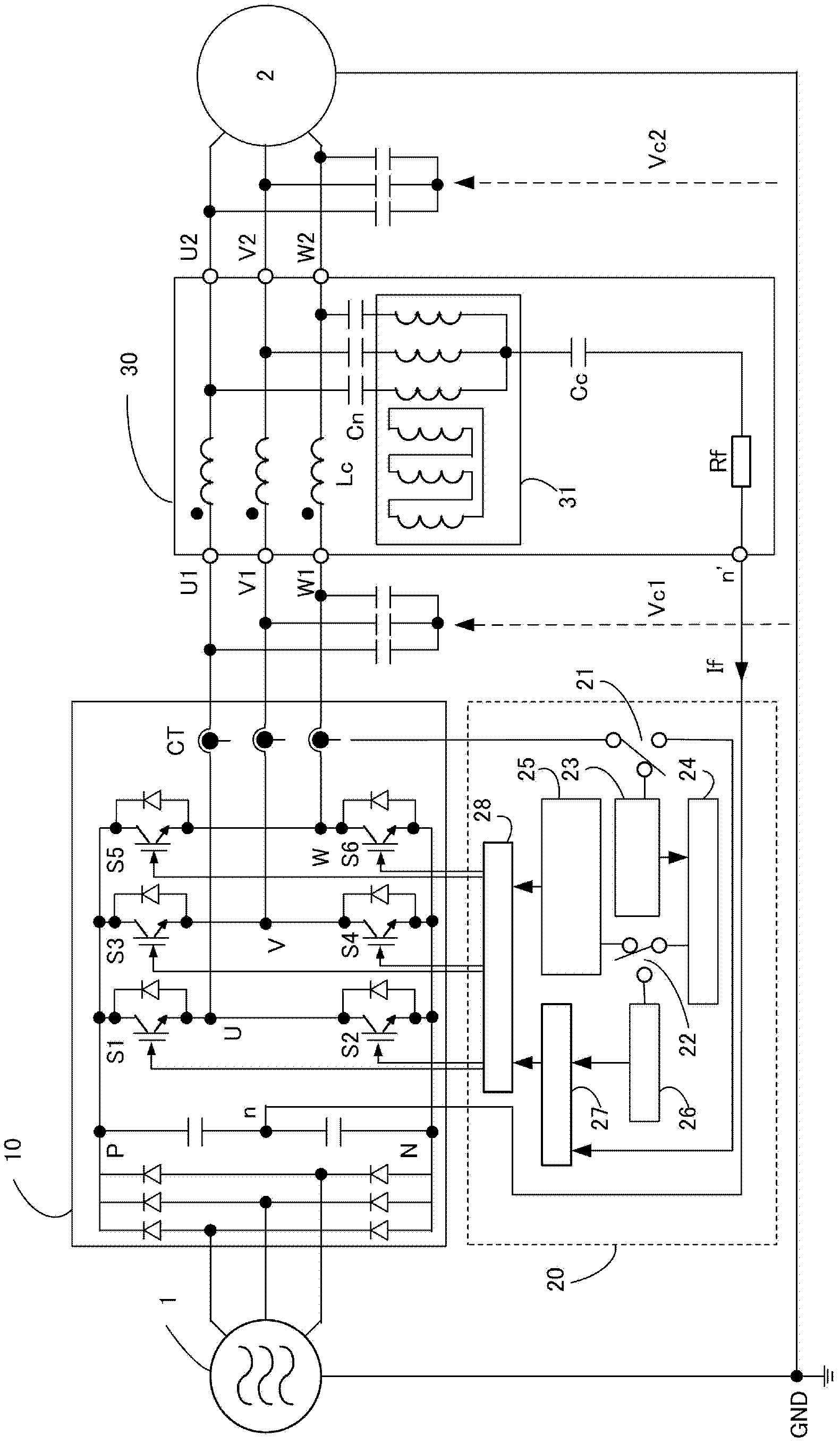
[0034] Figure 8 A schematic configuration diagram of a motor drive device including a common mode filter and a power conversion device is shown.

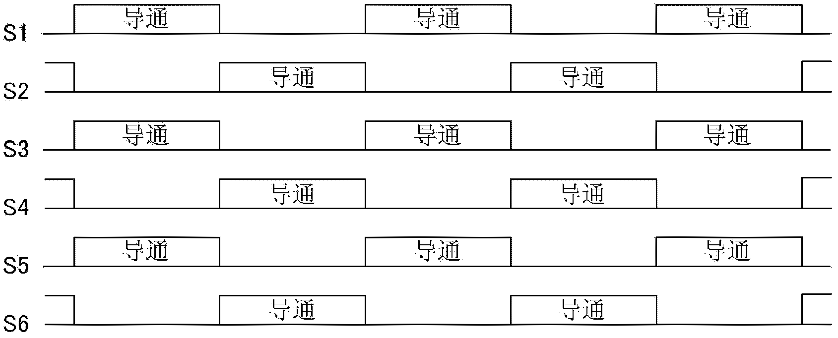
[0035] This motor drive device is constituted by a power conversion device (main circuit unit 10 , drive control unit 40 ) and a common mode filter 30 provided on the output side thereof. The AC power supply 1 is input to the main circuit part 10, and the switching elements S1-S6 in the main circuit part 10 are turned on and off according to the PWM driving signal from the drive control part 40, and the AC-DC conversion is performed, and then through the common The modulo filter 30 supplies power to the motor 2 .

[0036] In addition, in the drive control unit 40, the controller 47 is based on the output current detection signal from the current detector CT included in the main circuit unit 10, a command signal from a higher level (not shown), and th...


PUM


Abstract

Provided is a motor driving device that assesses whether a common-mode filter is furnished at the output side of an electric-power conversion device of the motor driving device, and that can also avoid increase in loss of the electric-power conversion device that is due to improvement in the common-mode filter characteristics, and an excessive filter current, and also avoid magnetic saturation at a common-mode choke coil. Provided is a means of assessing the existence of the common-mode filter that is to be connected between the aforementioned electric-power conversion device and the aforementioned motor, by driving the aforementioned switching devices with prescribed PWM ON-OFF driving signals that are in accordance with a carrier frequency of the aforementioned electric-power conversion device, before the real operation; and a means of changing and setting the PWM control method of the aforementioned electric-power conversion device, in accordance with the result of the aforementioned assessment of the existence of the common-mode filter, during real operation.

Description

technical field [0001] The present invention relates to a motor drive device having a power conversion device for supplying power to a motor. Background technique [0002] Common problems on the output side of the power conversion device in the motor drive device include high-frequency leakage current, conducted EMI (Electro Magnetic Interference: electromagnetic interference noise), radiated EMI, and electric corrosion of motor bearings. In view of such a problem, in the conventional motor drive device, a common mode filter is provided on the output side of the power conversion device to deal with it. [0003] Regarding the first motor drive device disclosed in Japanese Patent Laid-Open No. 2001-069762 (page 9, FIG. 18 ), a series connection of a common mode choke coil, a capacitor and a resistor is connected between the inverter and the electric equipment. One end is connected to each line between the common mode choke coil and the electrical equipment, and the other end ...

Claims


Application Information

Patent Timeline
Patent Type & Authority Applications(China)
IPC IPC(8): H02P27/08H02M1/12H02M7/48H02P21/05H02P21/22H02P23/04
CPCH02P27/08H02M2001/123H02M1/126H02M1/123
Inventor 樋口刚山田健二
Owner YASKAWA DENKI KK
Why Eureka
Try Eureka