Belly pipe with pulverized coal burning function

A technology of pulverized coal combustion and straight blowing, which is applied in the direction of tuyere etc.

Inactive Publication Date: 2012-06-06
张昭贵
View PDF3 Cites 4 Cited by
  • Summary
  • Abstract
  • Description
  • Claims
  • Application Information

AI Technical Summary

Problems solved by technology

However, according to the existing theory of pulverized coal combustion in blast furnaces, the pulverized coal has been preheated and dry-distilled through the length of a tuyere channel, and the volatile matter in the furnace has already met the conditions for ignition and combustion. Start a large amount of combustion, which will si

Method used


Image

  • Belly pipe with pulverized coal burning function
  • Belly pipe with pulverized coal burning function
  • Belly pipe with pulverized coal burning function

Examples


Embodiment 1

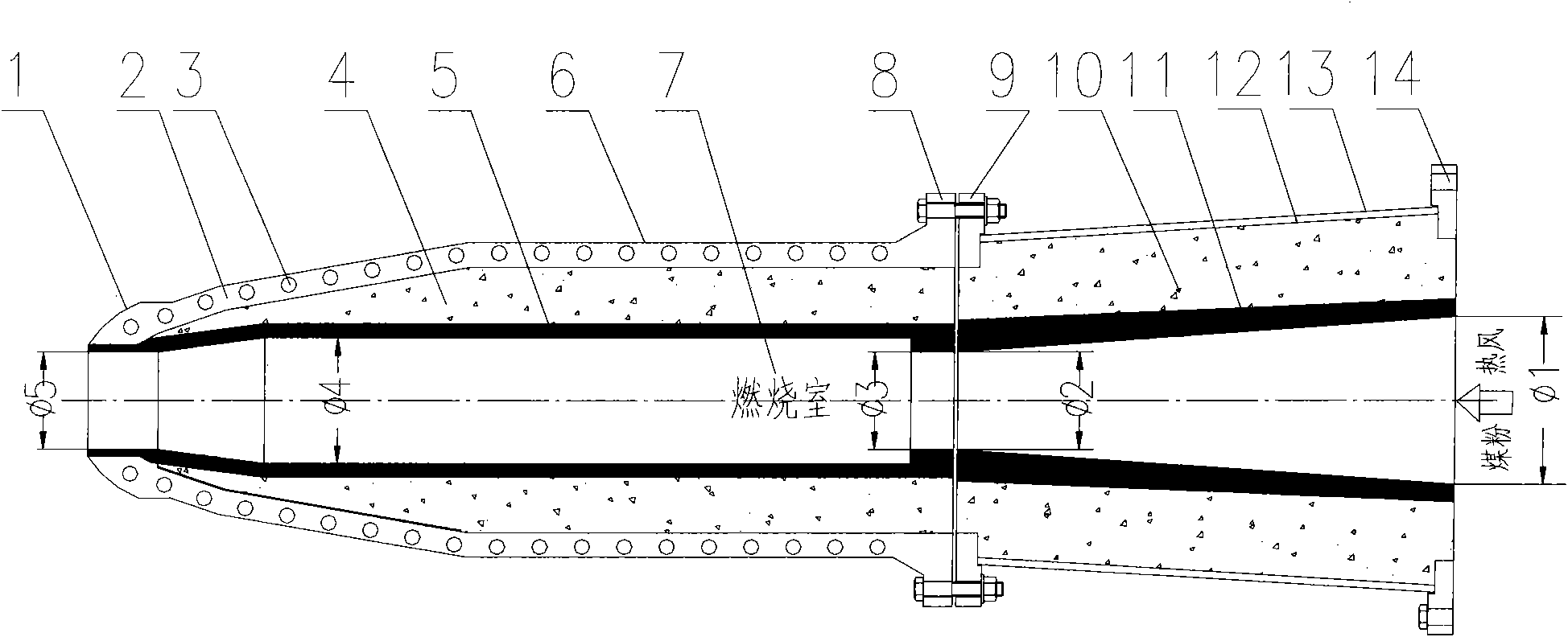
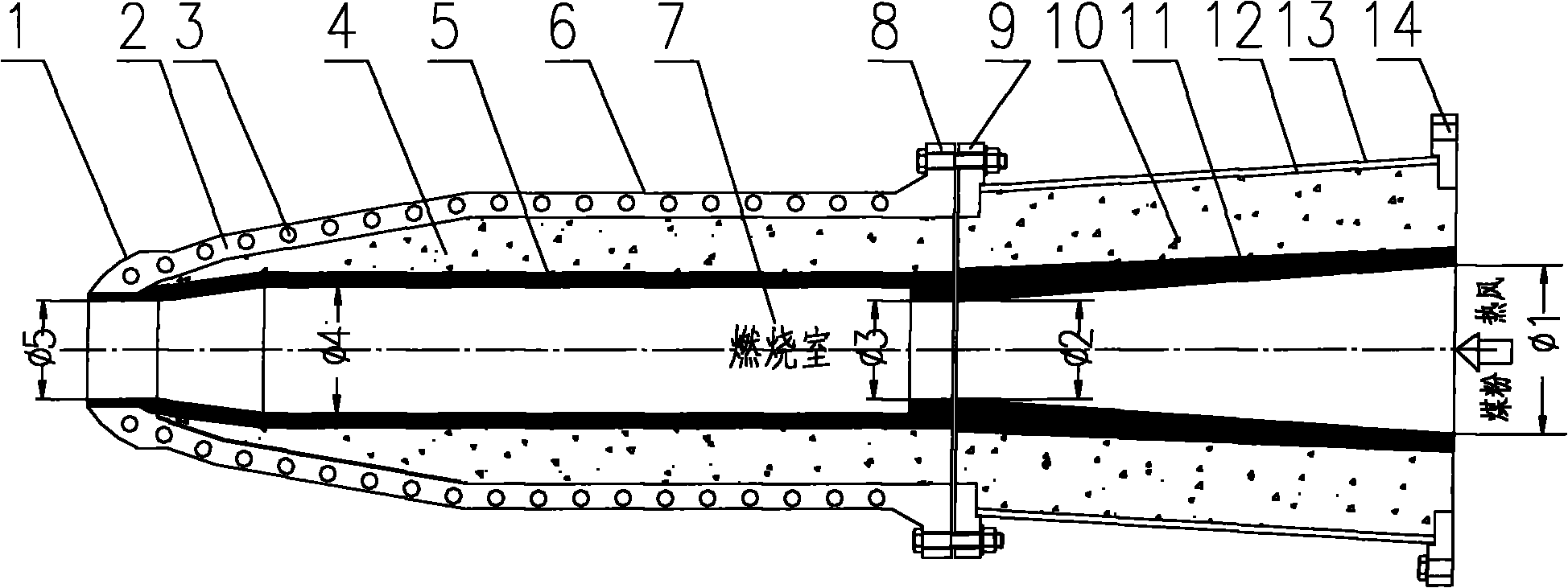
[0021] Such as figure 1 As shown, the straight blowing pipe with pulverized coal combustion function is composed of a burner 6 and a pre-burner 13, and the burner 6 and the pre-burner 12 are connected by flanges 8 and 9, and hot air and pulverized coal are fed from the pre-burner at the same time. Entrance to enter.

[0022] Such as figure 1 As shown, the internal channel of the pre-combustor 6 is a reducer structure, and its function is to accelerate and mix the hot air and coal powder, which is equivalent to the function played by the existing tuyeres. The outlet diameter ¢2 of the preburner 13 is smaller than the inlet diameter ¢1 and equal to the burner inlet diameter ¢3.

[0023] Such as figure 1 As shown, in the burner 6, a combustion chamber 7 with a sudden diameter expansion is provided. Part of the pulverized coal that is mixed and has combustion conditions burns rapidly, just like the similar effect of deceleration and rapid combustion when the existing pulverize...

Embodiment 2

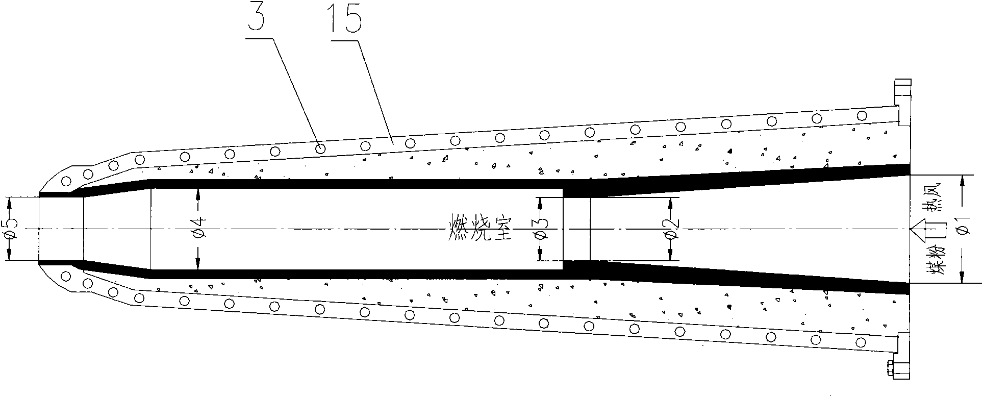
[0030] Such as figure 2 As shown, the above-mentioned burner 6 and pre-combustor 13 can save the intermediate connecting flanges 8 and 9 when it is convenient to manufacture, and make them into a whole, and their internal structure remains unchanged. At this time, the integral housing 15 has a cooling water channel 3 inside. The material of the housing 2 is heat-resistant stainless steel or copper or a combination of other metal materials.

[0031] In the above description, the tuyere and the elbow are the contents of the prior art. Instructions attached figure 1 Attached is the abstract.


PUM


Abstract

The utility model provides a belly pipe with a pulverized coal burning function, which comprises a premix burner and a burner. The premix burner and the burner are connected through a flange; hot-blast air and pulverized coal simultaneously enter from the inlet of the premix burner; an internal channel in the premix burner is of a reducing pipe structure; the diameter of the outlet of the premix burner is less than that of the inlet of the premix burner and is equal to that of the inlet of the burner; a suddenly expanding combustion chamber is arranged in the burner; the inner diameter of the combustion chamber is greater than the diameter of the inlet of the burner, whereas the outlet section of the burner is also of a reducing pipe structure; and the diameter of the outlet of the burner is less than the inner diameter of the combustion chamber and is also less than the diameter of the inlet of an air inlet. Due to the fact that the pulverized coal starts to be injected into the hot-blast air nearby the inlet of the premix burner, equivalently the existing pulverized coal injected into a blast furnace is injected into the blast furnace again after being burnt outside the furnace, thus, the burning rate of the injected pulverized coal is greatly improved and the burning amount of the pulverized coal in the hot-blast air is increased, thereby the amount of the injected pulverized coal which can be accepted by the blast furnace is obviously increased. At the same time, partially burnt pulverized coal causes the volume and the temperature of combustion products to be increased sharply and the blast kinetic energy is also obviously improved, and therefore, the beneficial effect of improving the work of a blast furnace hearth is brought.

Description

technical field [0001] The invention belongs to the technical field of blast furnace ironmaking, and relates to blast furnace coal injection technology and blast furnace air supply equipment, in particular to a direct blow pipe with coal powder combustion function. Background technique [0002] In the actual production of the blast furnace, the pulverized coal is directly sprayed into the hot air by the spray gun near the tuyere inlet. Usually, for the purpose of preventing coal powder from wearing the tuyere, the head of the spray gun is bent into a certain angle and inserted directly into the extension line of the center line of the straight blowing pipe, and its position has penetrated into the tuyere channel for a distance of about 100-300mm. Therefore, it is impossible for pulverized coal to burn in the direct blowpipe. [0003] Insert the spray gun from the peephole and extend to the entrance of the existing straight blowpipe. The entire straight blowpipe channel beco...

Claims


Application Information

Patent Timeline
IPC IPC(8): C21B7/16
Inventor 张昭贵
Owner 张昭贵
Why Eureka
Try Eureka