Laser shock method and laser shock device

A laser shock and laser technology, used in laser welding equipment, welding equipment, metal processing equipment, etc., can solve the problems of high cost, wide acceptance, poor adaptability to the constraint plane, etc., and achieve the effect of convenient positioning

Inactive Publication Date: 2012-06-13
HENAN UNIV OF SCI & TECH
View PDF4 Cites 31 Cited by
  • Summary
  • Abstract
  • Description
  • Claims
  • Application Information

AI Technical Summary

Problems solved by technology

However, as a rigid material, the glass constrained layer has extremely poor adaptability to constrained planes, especially for laser shock advantages, such as micro-holes, corners and other local areas, and non-planar areas cannot be applied; and the operation is difficult, and it needs to be used every time it is impacted. Replacing the constraining layer once is also very expensive and can only be applied to the laboratory research stage
In addition, glass, as a brittle material, bursts and sputters after being subjected to the action of plasma shock waves, which poses a certain degree of danger to operators and lasers
[0011] In order to solve the problem of poor adaptability of the glass constrained layer, many people are also working on the research and development of flexible confinement technology, including water, flexible film, silica gel, PVC f...

Method used


Image

  • Laser shock method and laser shock device
  • Laser shock method and laser shock device
  • Laser shock method and laser shock device

Examples


Embodiment Construction

[0045] In order to make the purpose, technical solutions and advantages of the embodiments of the present invention more clear, specific embodiments will be described in detail below with reference to the accompanying drawings.

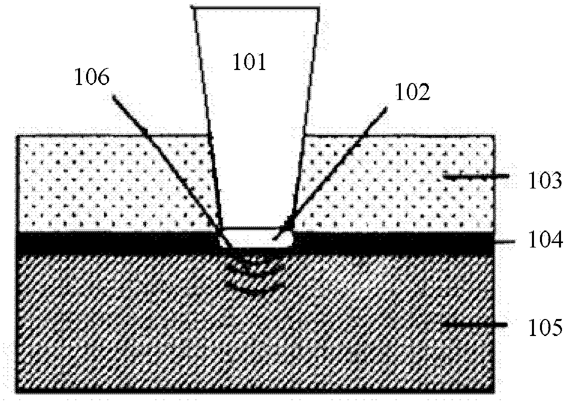
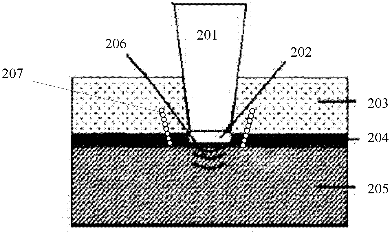
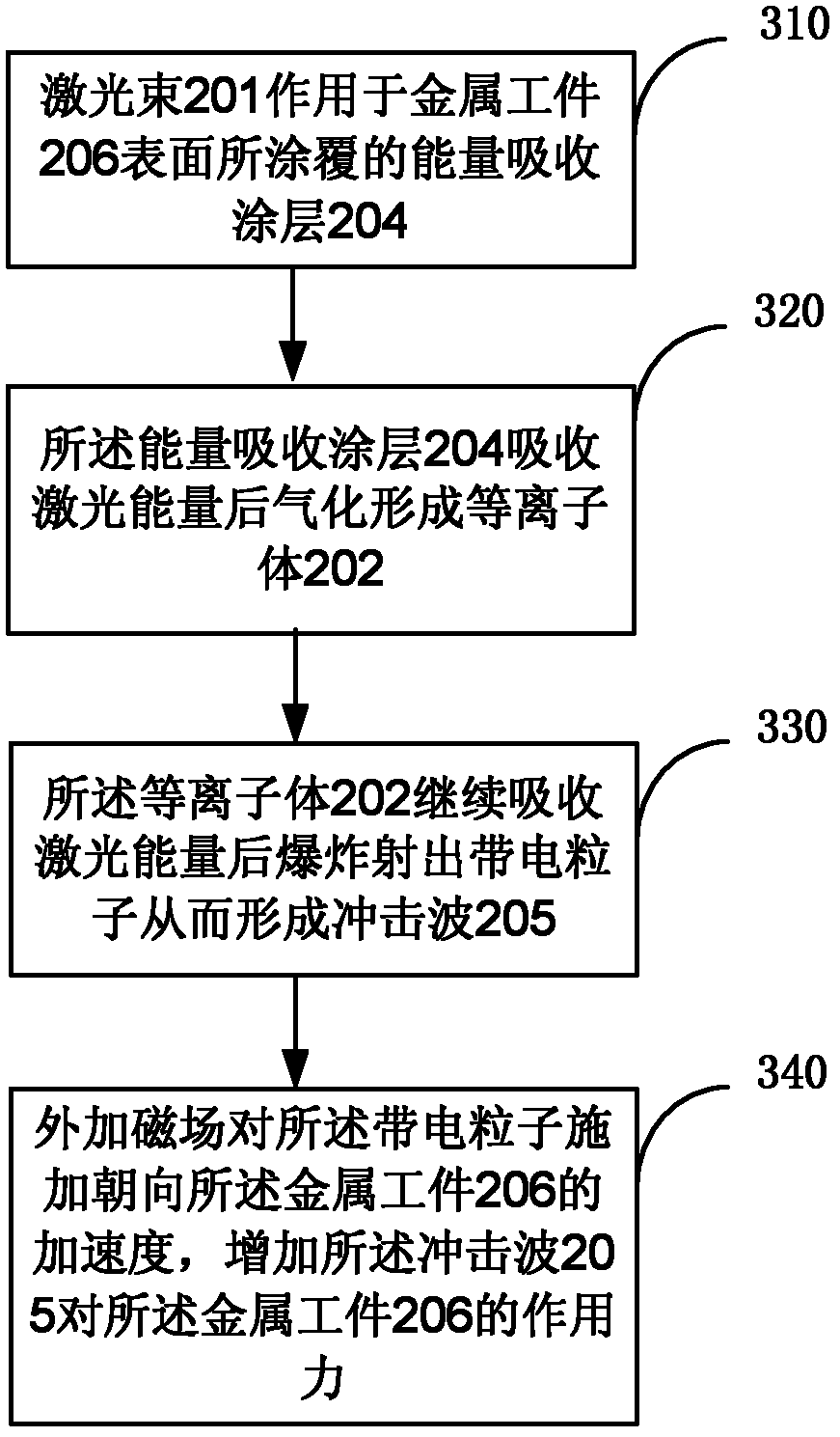
[0046] figure 2 A schematic diagram of a laser shock device provided by the present invention, image 3 The flow chart of the steps of the laser shock method provided by the present invention, such as figure 2 , image 3 As shown, the embodiment of the present invention provides a laser shock method, including:

[0047] Step 310, the laser beam 201 acts on the energy absorbing coating 204 coated on the surface of the metal workpiece 206;

[0048] Step 320, the energy absorbing coating 204 absorbs the laser energy and vaporizes to form a plasma 202;

[0049] Step 330, the plasma 202 continues to absorb the laser energy and then explodes to eject charged particles to form a shock wave 205;

[0050] Step 340 , applying an external magnetic field t...


PUM


Abstract

The invention discloses a laser shock method and a laser shock device. The laser shock method comprises the following steps that: 1, a laser beam acts on an energy absorption coating coated on the surface of a metal workpiece; 2, the energy absorption coating absorbs laser energy and then is gasified to form a plasma; 3, the plasma continues to absorb the laser energy and then explodes to eject charged particles so as to form shock waves; and 4, an external magnetic field imposes the acceleration facing the metal workpiece on the charged particles so as to increase the action force of the shock waves on the metal workpiece. By the method and the device, the intensity of the shock waves can be increased so as to perform contactless constraint on the plasma, so that the shock effect is improved and the environmental pollution is avoided.

Description

technical field [0001] The invention relates to the technical field of mechanical manufacturing and laser shock strengthening, in particular to a laser shock method and a device thereof. Background technique [0002] Laser shock strengthening technology is a high-tech technology that uses plasma shock waves generated by strong laser beams to improve the fatigue resistance, wear resistance and corrosion resistance of metal materials. It has outstanding advantages such as non-contact, no heat-affected zone, strong controllability and remarkable strengthening effect. [0003] figure 1 A schematic diagram of the existing laser shock strengthening, such as figure 1 Shown, high power density (GW / cm 2 order), short pulse (10-30ns order) laser beam 101 acts on the energy-absorbing coating 104 coated on the surface of the metal workpiece 106 through the transparent confinement layer 103, the coating 104 absorbs the laser energy and vaporizes rapidly and A large amount of dense hi...

Claims


Application Information

Patent Timeline
IPC IPC(8): B23K26/18B23K26/42B23K26/70
Inventor 张凌峰熊毅高轲赵培峰苌清华周合玉
Owner HENAN UNIV OF SCI & TECH
Why Eureka
Try Eureka