Efficient anaerobic bioreactor

An anaerobic biology and reactor technology, applied in the field of sanitation, can solve the problems of low treatment load, difficult to further improve the treatment water quality, no sludge circulation, etc., and achieve the effect of coherent working process, remarkable separation effect and good working efficiency

Active Publication Date: 2012-06-13
SICHUAN STONG EURO & AMERICA ENVIRONMENT ENG
View PDF4 Cites 10 Cited by
  • Summary
  • Abstract
  • Description
  • Claims
  • Application Information

AI Technical Summary

Problems solved by technology

[0003] There are three main types of common anaerobic bioreactors: the first type is represented by the commonly used anaerobic tank, the reaction tank is completely mixed, there is no sludge circulation, the treatment load is low, and the treatment efficiency is low
The second type is the upflow anaerobic sludge bed (UASB), which is mainly composed of a sludge reaction zone and a gas-liquid-solid three-phase separator. UASB retains a large amount of anaerobic sludge in the bottom reaction zone and has good sedimentation The sludge with high performance and coagulation performance forms a sludge layer in the lower part, and the sludge that settles on the inclined wall slides back into the anaerobic reaction zone along the inclined wall, so that a large amount of sludge accumulates in the reaction zone, and the sludge separated from the sludge The treated effluent overflows from the upper part of the overflow weir in the sedimentation area, and then discharges into the sludge bed. It is characterized by a gas-liquid-solid three-phase separator, which has high treatment efficiency, but the sludge is often lost.
The third category is represented by anaerobic granular sludge expanded bed (EGSB) and anaerobic internal circulation reactor (IC), which is characterized by alleviating the short-flow defects of UASB reactors. However, EGSB reactors require liquid reflux, Increased power consumption makes it difficult to further improve the treated water quality, and it is difficult to control the operation of the IC reactor

Method used


Image

  • Efficient anaerobic bioreactor
  • Efficient anaerobic bioreactor
  • Efficient anaerobic bioreactor

Examples


Embodiment

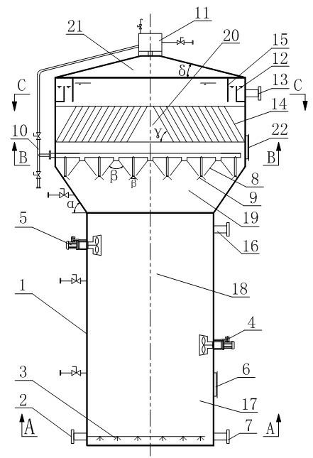
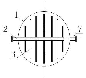
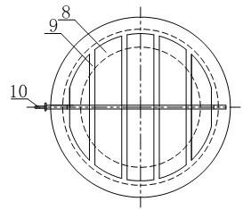
[0028] Such as Figure 1~4 As shown, a high-efficiency anaerobic bioreactor includes a water-sealed box 11, an exhaust pipe 10 and a hollow reactor body 1, wherein the reactor body 1 is formed with a mud-water mixing zone 17 and a suspension zone 18 from bottom to top. , three-phase separation zone 19, sedimentation zone 20 and gas chamber 21, mud-water mixing zone 17, suspension zone 18, three-phase separation zone 19 and sedimentation zone 20 are connected in sequence, and a partition is provided between the sedimentation zone 20 and the gas chamber 21 The sealing plate of the precipitation area 20 and the air chamber 21 can prevent water from entering the air chamber 21. The outer wall of the reactor body 1 is connected with an inlet pipe 2 connected to the mud-water mixing zone 17 , an outlet pipe 13 connected to the sedimentation zone 20 and a sludge discharge pipe 16 connected to the suspension zone 18 . The water-sealed box 11 is arranged on the top of the reactor body...


PUM


Abstract

The invention discloses an efficient anaerobic bioreactor, which comprises a reactor, a water sealing tank and an exhaust pipe, wherein a mud-water mixing region, a suspension region, a three-phase separation region, a precipitation region and an air chamber are formed inside the reactor body from bottom to top; the mud-water mixing region, the suspension region, the three-phase separation regionand the precipitation region are communicated in sequence; the outer side wall of the reactor body is connected with a water inlet pipe, a water outlet pipe and a mud discharge pipe; the water inlet pipe is communicated with the mud-water mixing region; the water outlet pipe is communicated with the precipitation region; the mud discharge pipe is communicated with the suspension region; the watersealing tank is arranged at the top end of the reactor body, and is communicated with the air chamber; a three-phase separator connected with the exhaust pipe is arranged in the three-phase separation region; and the three-phase separator is communicated with the water sealing tank through the exhaust pipe. Partitioned treatment is performed during decomposition of organic matters in waste water,so that the function of each functional region is enhanced, and the reactor has high treatment efficiency, is convenient to operate, and runs stably.

Description

technical field [0001] The invention relates to the field of sanitation, in particular to a high-efficiency anaerobic bioreactor. Background technique [0002] Anaerobic biological reaction technology is a process in which the nutritional and environmental conditions required by anaerobic microorganisms are formed under anaerobic conditions, and the metabolism of such microorganisms is used to decompose organic matter in wastewater and produce methane and carbon dioxide. [0003] There are three main types of common anaerobic bioreactors: the first type is represented by the commonly used anaerobic tank, the reaction tank is completely mixed, there is no sludge circulation, the treatment load is low, and the treatment efficiency is low. The second type is the upflow anaerobic sludge bed (UASB), which is mainly composed of a sludge reaction zone and a gas-liquid-solid three-phase separator. UASB retains a large amount of anaerobic sludge in the bottom reaction zone and has go...

Claims


Application Information

Patent Timeline
IPC IPC(8): C02F3/28
Inventor 李华胡登燕郑传勇
Owner SICHUAN STONG EURO & AMERICA ENVIRONMENT ENG
Why Eureka
Try Eureka