Hoop for airplane hydraulic pipeline and design method thereof

A technology of aircraft hydraulics and design methods, applied in the direction of pipeline supports, mechanical equipment, pipes/pipe joints/fittings, etc., can solve the problems of easy aging, failure of pipeline system, fretting wear of clamp support, etc.

Inactive Publication Date: 2012-06-13
BEIHANG UNIV
View PDF5 Cites 10 Cited by
  • Summary
  • Abstract
  • Description
  • Claims
  • Application Information

AI Technical Summary

Problems solved by technology

[0006] 1) The rubber material is not resistant to high temperature and is easy to age. Long-term pipeline vibration will cause the rubber material to fail, resulting in fretting wear on the clamp support. With the development of fretting wear, the support stiffness gradually decreases, so that the natural frequency of the pipeline gradually decreases. When the reduced natural frequency of the pipeline is close to or coincides with the pressure pulsation frequency, fluid-solid coupling vibration occurs, which also causes the failure of the pipeline system
[0007] 2) The hoop blocks (belts) which play a fixed role on the periphery of the aircraft hoop are made of metal materials with high rigidity. However, due to the large number of hoops in an aircraft, one of the design indicators of the aircraft is to reduce the mass as much as possible. More metal material clamp will bring extra weight

Method used


Image

  • Hoop for airplane hydraulic pipeline and design method thereof
  • Hoop for airplane hydraulic pipeline and design method thereof
  • Hoop for airplane hydraulic pipeline and design method thereof

Examples


Embodiment Construction

[0054] The present invention will be further described in detail with reference to the accompanying drawings and embodiments.

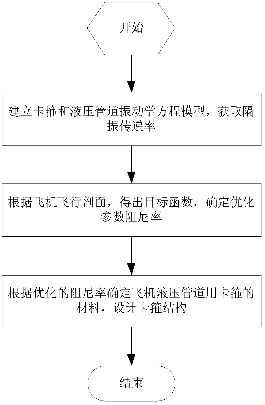
[0055] The present invention is a kind of design method of clamp used for aircraft hydraulic pipeline, and the process is as follows figure 2 shown, including the following steps:

[0056] Step 1: Establish the vibration equation model of the clamp and the hydraulic pipeline to obtain the vibration isolation transmission rate.

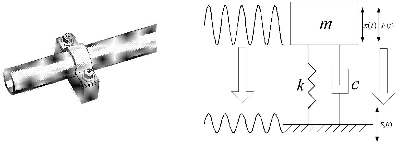
[0057] Create a clamp model, such as image 3 As shown, the aircraft hydraulic fluid-filled pipeline is a lumped mass m, k is the clamp stiffness, c is the clamp damping coefficient, the exciting force generated by the fluid pulsation in the aircraft hydraulic pipeline is F(t), and the pipeline is subjected to vibration shock displacement is x(t), F b (t) represents the force transmitted to the aircraft foundation support.

[0058] Build the model equation of motion:

[0059] m x ...


PUM


Abstract

The invention discloses a hoop for an airplane hydraulic pipeline and a design method thereof. The method comprises the steps of 1 establishing a vibration equation model of the hoop and the hydraulic pipeline and obtaining vibration isolation transmissibility; 2 according to the flight profile of an airplane, obtaining a target function and determining and optimizing damping ratio xi of parameters; and 3 determining materials used by the hoop for the airplane hydraulic pipeline according to optimized damping ratio, and designing a hoop structure. The hoop comprises fastening bolts, spring gaskets, an upper metal rubber pad block, an upper anti-lock brake system (ABS) plastic hoop block, a lower ABS plastic hoop block and a lower metal rubber pad block. The lower ABS plastic hoop block isinternally embedded in the lower metal rubber pad block, the upper ABS plastic hoop block is internally embedded in the upper metal rubber pad block, and the airplane hydraulic pipeline is located between the lower metal rubber pad block and the upper metal rubber pad block. Two fastening bolts penetrate through the upper ABS plastic hoop block and the lower ABS plastic hoop block, and the springgaskets are arranged between the two fastening bolts and the upper ABS plastic hoop block. The vibration isolation rate weighted sum corresponding to excitation source frequency points determined by the flight profile of the airplane serves as a basis of parameters for designing the hoop, and the hoop is designed according to the basis of the parameters.

Description

technical field [0001] The invention belongs to the field of vibration reduction of high-frequency vibration pipelines of aircraft hydraulic systems, and in particular relates to a clamp for aircraft hydraulic pipelines and a design method thereof. Background technique [0002] Due to the pulsating flow output of the aircraft hydraulic pump source, the aircraft hydraulic pipeline will be subject to the pulsation impact of the fluid. Excessive vibration impact will cause the pipeline to rupture and cause the aircraft to crash. Therefore, the vibration reduction design of the aircraft pipeline is an urgent problem to be solved. At the beginning of the design of the new model, in addition to selecting supporting structure materials and piping materials that meet the requirements of static strength and fatigue strength, necessary tests and adjustments must be made on the piping system so that the natural frequency of the piping system avoids the fluid pulsation frequency and excl...

Claims


Application Information

Patent Timeline
Patent Type & Authority Applications(China)
IPC IPC(8): F16L3/10
Inventor 李鑫王少萍
Owner BEIHANG UNIV
Why Eureka
Try Eureka