Method of using optical fiber Bragg grating to monitor temperature of intermediate connector of medium-voltage power cable

A technology for intermediate joints and power cables, applied in thermometers, thermometers with physical/chemical changes, measuring devices, etc., can solve problems such as inaccurate measurement results, high current, and strong magnetic field effects, and achieve corrosion resistance and electromagnetic resistance Strong interference ability and the effect of reducing measurement errors

Inactive Publication Date: 2012-06-13
KUNMING UNIV OF SCI & TECH +1
View PDF5 Cites 5 Cited by
  • Summary
  • Abstract
  • Description
  • Claims
  • Application Information

AI Technical Summary

Problems solved by technology

This method is easily affected by the large current and strong magnetic field of the cable itself, and the measurement results are not accurate enough

Method used


Image

  • Method of using optical fiber Bragg grating to monitor temperature of intermediate connector of medium-voltage power cable
  • Method of using optical fiber Bragg grating to monitor temperature of intermediate connector of medium-voltage power cable
  • Method of using optical fiber Bragg grating to monitor temperature of intermediate connector of medium-voltage power cable

Examples


Embodiment 1

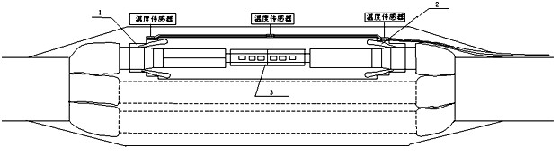
[0034] like figure 1 As shown: three optical fiber Bragg grating temperature sensors can be fixed on the outer surface of the cold-shrink insulation 1 through epoxy resin, and the fixing points correspond to the midpoint of the stress cone 2 at both ends and the midpoint of the intermediate connecting pipe 3 respectively. Then according to the change of the wavelength value reflected by the grating, the temperature of the stress cone at both ends of the joint and the temperature of the intermediate connecting pipe is calculated through the relationship between the shift of the fiber Bragg grating temperature sensor Bragg wavelength and the temperature; finally, according to the measured temperature and the conventional temperature In contrast, when any one or more of them is abnormal, it can be determined that the intermediate joint is in an abnormal working condition.

[0035] The selection of the fiber Bragg grating temperature sensor: common fiber Bragg grating temperature ...

Embodiment 2

[0037] In order to better realize the method, the present invention provides an optical fiber Bragg temperature sensor.

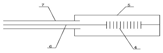
[0038] like figure 2 Shown: including fiber Bragg grating 4, capillary copper tube 5, polytetrafluoroethylene sleeve 6, fiber lead wire 7; use epoxy resin to tightly fix fiber Bragg grating 4 in capillary copper tube 5, fiber lead wire 7 strings In the polytetrafluoroethylene casing, the polytetrafluoroethylene casing 6 and the capillary copper tube 5 are connected as a whole through epoxy resin.

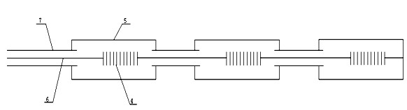
[0039] like image 3 As shown: the three optical fiber Bragg grating temperature sensors connected in series are connected in series and fixed on the outer surface of the cold-shrink insulation 1, and the fixing points correspond to the midpoint of the stress cone 2 at both ends and the intermediate connecting pipe respectively. The midpoint of 3; according to the change of the temperature of the three monitoring points to the wavelength of the grating, and th...

Embodiment 3

[0041] In order to realize described method better, the present invention improves above-mentioned optical fiber Bragg temperature sensor again, as Figure 4 As shown: it consists of fiber Bragg grating 4, capillary copper tube 5, polyimide sleeve 6, optical fiber lead wire 7, and annular metal sheet 8; fiber Bragg grating 4 is encapsulated in capillary copper tube 5 through epoxy resin , and the capillary copper tube 5 and the annular metal sheet 8 are integrally formed and connected as a whole, and the capillary copper tube 5 and the polyimide sleeve 6 sleeved on the optical fiber lead-out line 7 are sealed and connected by epoxy resin.

[0042]The annular metal sheet can be selected from steel, copper, etc., among which copper material with a large expansion coefficient (thermal expansion coefficient is 0.189×10⁻⁴m / °C) is preferred.

[0043] Three optical fiber Bragg grating temperature sensors connected in series are fixed on the outer surface of the cold-shrink insulation...


PUM


Abstract

The invention relates to a method of using an optical fiber Bragg grating to monitor the temperature of an intermediate connector of a medium-voltage power cable, belonging to the technical field of a photoelectron measuring device. At first, three optical fiber Bragg temperature sensors are fixed on an outer surface of a cold-shrinking insulation component, and and the fixing points respectively correspond to the midpoints of stress cones at the two ends and the midpoint of an intermediate connecting pipe; then the temperature of the stress cones at the two ends and the intermediate connecting pipe in the connector can be calculated according to changes in the value of the wavelength reflected by the optical grating and the relationship between the shifting of the Bragg wavelength of the optical fiber grating temperature sensors and the temperature; and finally the intermediate connector can be judged to be in abnormal operation when one or more sensor(s) is / are in the abnormal state based on comparison of the measured temperature and the normal temperature. The method is suitable for measurement of the temperature of the intermediate connector of the medium-voltage cable, the real-time online measurement of the temperature of the intermediate connector of the power cable can be realized, and errors in measurement resulting from the external ambient temperature can be reduced. Moreover, the method is simple and has high sensitivity.

Description

technical field [0001] The invention relates to a method for monitoring the temperature of an intermediate joint of a medium-voltage power cable by using an optical fiber Bragg grating device, belonging to the technical field of optoelectronic measurement. Background technique [0002] With the expansion of the capacity of electrical equipment and the increasing demand for electricity in the society, power cables have become blood vessels for power transmission. They often operate continuously for a long time under high voltage and high current. The middle joint of power cables is the weakest link and is prone to failure. . According to the actual operation experience and theoretical analysis, the failure at the middle joint of the power cable is often not a sudden accident. The aging of the cable insulation material and the gradual increase of the leakage current will eventually lead to thermal breakdown or cable fire. Once such an accident occurs, it will affect the norma...

Claims


Application Information

Patent Timeline
Patent Type & Authority Applications(China)
IPC IPC(8): G01K11/32G01K11/3206
Inventor 李川陈炎锋孙家禄李建发赵艳峰
Owner KUNMING UNIV OF SCI & TECH
Why Eureka
Try Eureka