LLC resonance type push-pull forward conversion topology

A push-pull forward, topology technology, applied in the direction of DC power input conversion to DC power output, regulating electrical variables, high-efficiency power electronic conversion, etc., can solve problems such as large voltage spikes of rectifier diodes

Inactive Publication Date: 2012-06-13
NANJING UNIV OF AERONAUTICS & ASTRONAUTICS
View PDF1 Cites 19 Cited by
  • Summary
  • Abstract
  • Description
  • Claims
  • Application Information

AI Technical Summary

Problems solved by technology

Due to the reverse recovery of the diode and its operation at high freque

Method used


Image

  • LLC resonance type push-pull forward conversion topology
  • LLC resonance type push-pull forward conversion topology
  • LLC resonance type push-pull forward conversion topology

Examples


Embodiment Construction

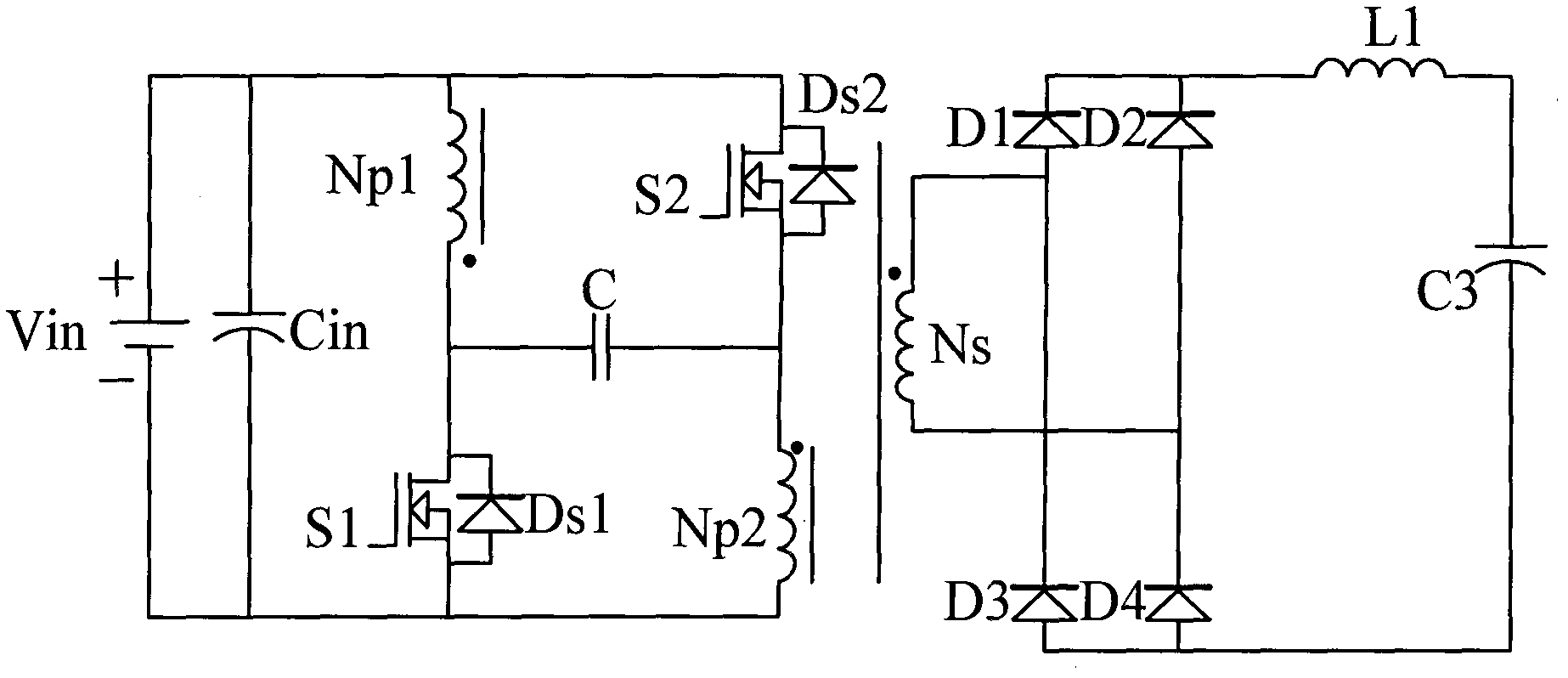
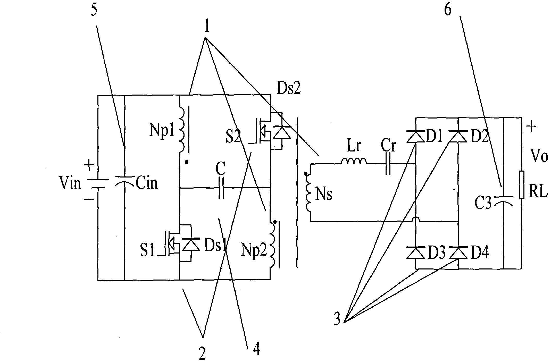
[0011] The present invention is based on the push-pull forward circuit, and adds resonant networks L and C between the secondary side of the transformer and the rectifier bridge. Specifically, the voltage source Vin is connected in parallel with the input filter capacitor Cin, the positive terminal of the voltage source is connected to the positive terminal of Cin, and the negative terminal of the voltage source is connected to the negative terminal of Cin. The same-named end of Np1 is connected to one end of the clamping capacitor C and the drain of the power transistor S1; the different-named end of Np1 is connected to the positive end of the input capacitor Cin and the drain of the power transistor S2. The source of the power transistor S2 is connected to the terminal with the same name of Np2 and the other terminal of the clamping capacitor C. The opposite end of Np2 is connected to the source of S1 and the negative end of the input capacitor Cin. The end with the same na...


PUM


Abstract

The invention provides an LLC resonance type push-pull forward conversion topology. The topology is mainly characterized in that: on the basis of a current push-pull forward conversion topology, an L resonance circuit and a C resonance circuit are added at a secondary rectifier side. The topology uses the L resonance circuit and the C resonance circuit at a transformer secondary to eliminate a turn-off peak on a secondary rectifier diode; therefore, an RC absorption circuit or a CDD absorption circuit in an original push-pull forward conversion topology circuit can be removed, wherein the RC absorption circuit or the CDD absorption circuit is arranged for a diode backward recovery peak; and a filter inductor that is arranged at the back of the rectifier diode can also be removed. Meanwhile, soft switching of a main power tube can be realized; an EMC effect based on a topological converter can be improved; and losses of a main power switch tube and the rectifier diode can be reduced. Besides, the topology can be applied to a preceding stage of an inverter. According to the invention, the LLC resonance type push-pull forward conversion topology has advantages of simple structure, convenience, and reliable working and the like; and advantages like soft switching of various power devices and the like can be realized; therefore, the topology has a certain practical value.

Description

technical field [0001] The invention relates to an LLC resonant push-pull forward conversion topology. It belongs to the topology invention of DC / DC conversion, and its main technical fields are switching power supply, low voltage and high current input and other fields. Background technique [0002] In modern production and life, with the development of power electronics technology, DC / DC converters are widely used in various power electronics system power supply equipment to meet various requirements of power loads for power supply quality. Today, the development of switching power converters has found high power density, high efficiency, low cost, small size, and low EMI. [0003] In the prior art, there are many switching power supply topologies. Such as forward, flyback, half-bridge, full-bridge, push-pull, etc. attached figure 1 For the existing push-pull forward circuit. The terminal with the same name on the secondary side of the transformer Ns is directly conne...

Claims


Application Information

Patent Timeline
IPC IPC(8): H02M3/337
CPCY02B70/1433Y02B70/1491Y02B70/10
Inventor 邓翔赵国庆陈杰
Owner NANJING UNIV OF AERONAUTICS & ASTRONAUTICS
Why Eureka
Try Eureka