Brush direct current motor speed regulation device with compensation feedback function and method therefor

A brushed DC motor, compensation feedback technology, applied in the direction of excitation or armature current control, can solve the problems of change, can not achieve closed-loop control, increase cost, etc., achieve the effect of simple control, improve efficiency and reduce loss

Inactive Publication Date: 2012-06-13
JIANGSU HAOFENG AUTO PARTS
View PDF7 Cites 29 Cited by
  • Summary
  • Abstract
  • Description
  • Claims
  • Application Information

AI Technical Summary

Problems solved by technology

Considering the cost factor, the brushed DC motor PWM speed regulation in the automotive electronic system (such as the blower of the air conditioning system, the engine cooling fan) generally adopts open-loop control, directly through the duty ratio signal input by the ECU to control the duty cycle of the motor drive. Compared to controlling the motor speed, this open-loop control is only an approximate control of the motor speed, and cannot achieve a stable closed-loop control effect; some foreign manufacturers, such as Siemens, VALEO and other manufacturers have also added some form of The voltage feedback ensures that the expected voltage of the control is constant, so as to ensure the speed regulation performance of the motor, but this is only an ideal state. The actual motor has internal resistance, and this part also generates a certain voltage component, which is lost in the form of heat. ,

Method used


Image

  • Brush direct current motor speed regulation device with compensation feedback function and method therefor
  • Brush direct current motor speed regulation device with compensation feedback function and method therefor
  • Brush direct current motor speed regulation device with compensation feedback function and method therefor

Examples


Embodiment Construction

[0018] The present invention will be further described in detail below in combination with specific embodiments.

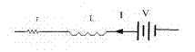
[0019] figure 1 Power supply for brushed DC motor and internal schematic diagram. It can be seen from the figure that the main electrical components of a brushed DC motor are composed of three parts: armature internal resistance R, inductance L and a voltage source V; voltage source V The power supply for the DC motor means the voltage applied to both ends of the motor, and the magnitude of the voltage determines the speed of the motor; L represents the magnetic field of the armature in the motor, which makes the motor rotate and do work, converting electrical energy into mechanical energy; the internal resistance of the armature R It is the internal resistance of the wire required to wind the motor coil. When the current I flows through the internal resistance R of the armature, a voltage drop will be generated and the power consumed will be converted into heat. ...


PUM


Abstract

The invention relates to the field of brush direct current motor speed regulating control, in particular to a compensation feedback speed regulating device of a brush direct current motor and a method therefor. The method realizes the speed regulating control to the brush direct current motor via acquiring and analyzing speed gain links of the voltage signal of the motor and current compensation control links of a motor working current signal; the speed gain links provide voltage feedback; and the current compensation feedback control links provide wasted current feedback used for compensating consumption and caused by the motor armature inner resistance; and a feedback controller of the device provided by the invention comprises the two links, and the device can also be used for achieving the method. The invention has the benefits that close-cycle control to the rotation speed of the motor is achieved via the speed gain link; an extra speed sensor is not required; the rotation speed deviation of the load change, which is caused by the motor armature inner resistance, is corrected by the current compensation control links; and the control is simple, the cost is low, and the universal property is high.

Description

technical field [0001] The invention relates to the field of brushed DC motor speed regulation control, in particular to a brushed DC motor compensation feedback speed regulation control device and method thereof, and is particularly suitable for PWM speed regulation control of automobile air conditioner blowers and automobile engine cooling fans. Background technique [0002] In order to improve the comfort and safety of driving, electronic control of automobiles has become a development trend, and many target occasions of control use DC motors as actuators. The essence of the speed regulation of the brushed DC motor is to change the terminal voltage of the motor. At present, the very popular control method is PWM switch control. Considering the cost factor, the brushed DC motor PWM speed regulation in the automotive electronic system (such as the blower of the air conditioning system, the engine cooling fan) generally adopts open-loop control, directly through the duty rat...

Claims


Application Information

Patent Timeline
IPC IPC(8): H02P7/28
Inventor 伍春生朱建方
Owner JIANGSU HAOFENG AUTO PARTS
Why Eureka
Try Eureka