Synchronous motor and system for driving synchronous motor

A synchronous motor and drive system technology, applied in synchronous machines, synchronous motors with stationary armatures and rotating magnets, motor control, etc., to solve problems such as torque reduction and inability to generate maximum torque

Active Publication Date: 2012-06-13
PANASONIC CORP
View PDF4 Cites 7 Cited by
  • Summary
  • Abstract
  • Description
  • Claims
  • Application Information

AI Technical Summary

Problems solved by technology

[0011] However, in the above structure, when a certain stator tooth is located at a position where the maximum torque is generated in relation to the rotor magnetic poles, the stator teeth arranged at intervals different from the magnetic pole intervals of the rotor a

Method used


Image

  • Synchronous motor and system for driving synchronous motor
  • Synchronous motor and system for driving synchronous motor
  • Synchronous motor and system for driving synchronous motor

Examples


no. 2 Embodiment approach

[0125] The difference between this embodiment and the first embodiment is that the rotor is arranged not only on the outer peripheral side of the stator but also on the inner peripheral side, and accordingly, the stator has stator teeth not only on the outer diameter side of the stator but also on the inner diameter side of the stator. tooth.

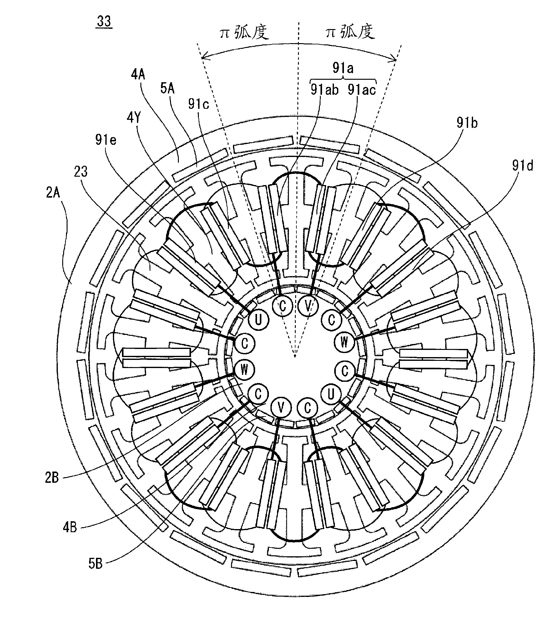
[0126] Figure 5 It is a plan view of the synchronous motor of this embodiment.

[0127] Figure 6 It is a schematic diagram of the winding structure of the synchronous motor of this embodiment.

[0128] Synchronous motor 33 is composed of rotors 2A, 2B and stator 23 .

[0129] The rotor 2A outside the stator 23 includes a rotor core 4A and 20 permanent magnets 5A, and the permanent magnets 5A are arranged at equal intervals on the rotor core 4A along the circumferential direction of the rotor. The pair of magnetic poles that alternately arrange N poles and S poles composed of permanent magnets 5A form an electrical angle of 2π radi...

no. 3 Embodiment approach

[0133] The difference between this embodiment and the first embodiment lies in the number of turns of the winding and the connections.

[0134] The winding is configured such that two types of stator windings are respectively wound on two adjacent stator yoke portions, and one type of stator winding is wound on each of the stator yoke portions on both sides of the two consecutive stator yoke portions. Hereinafter, differences from the first embodiment will be mainly described.

[0135] 3.1. Structure

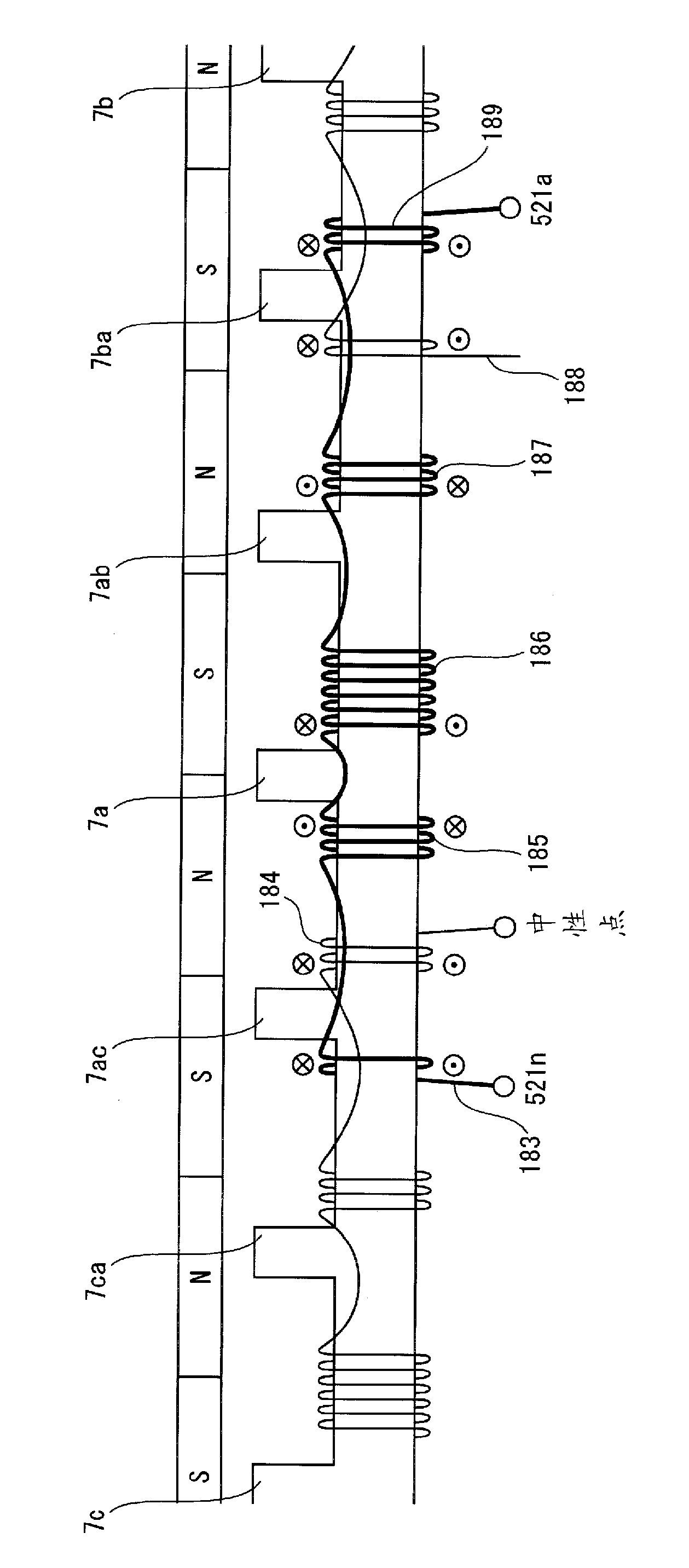
[0136] Figure 7 is a plan view of the synchronous motor of this embodiment, Figure 8 is the winding structure diagram of a synchronous motor, Figure 9 is a vector diagram representing the magnitude and phase of the magnetic field.

[0137] Synchronous motor 51 is composed of rotor 2 and stator 13 .

[0138] The rotor 2 is the same as the first embodiment, and the stator 13 is also the same as the first embodiment except for the structure of the stator winding.

[0139] ...


PUM


Abstract

Disclosed are a synchronous motor having reduced torque pulsation while having a high torque and a system for driving a synchronous motor. Specifically disclosed is a synchronous motor which comprises a rotor (2) and a stator(3), and U-phase windings (91; 91a, 91b, and the like), V-phase windings (92; 92ab and the like), and W-phase windings (93; 93ac and the like) are wound around stator yoke portions each located between two adjacent stator teeth (7; 7a, 7ab, and the like). Each of the windings is wound in predetermined turns and in a predetermined direction such that timing differences between the timings at which a magnetic field generated at each of the stator teeth is maximized and those at which portions (10, 11, 11, and the like) between magnetic poles pass the stator teeth while the rotor (2) rotates, the timing differences being caused by a difference between the interval between the magnetic poles and that between the stator teeth, are compensated.

Description

technical field [0001] The invention relates to a winding structure of a synchronous motor, in particular to a technology for improving torque performance. Background technique [0002] In synchronous motors used in compressors, electric vehicles, hybrid vehicles, fuel cell vehicles, etc., due to the requirements of small size, light weight, high output, low vibration, low noise, and high efficiency, it is particularly desirable to have high torque and low torque pulsation. [0003] In the case of a so-called surface magnet type synchronous motor in which permanent magnets are arranged on the surface of the rotor core, when the phase difference between the magnetic field generated by the permanent magnet and the armature current is 90o, that is, the stator winding is wound between the magnetic poles of the rotor The torque (magnetic torque) generated by the permanent magnets is the largest when the current supplied to the stator winding is the largest under the relative pos...

Claims


Application Information

Patent Timeline
IPC IPC(8): H02K21/16H02K3/16H02K3/18H02K3/28H02K16/02H02P23/00H02K21/22
CPCH02K21/222H02P5/00H02K3/28H02K16/00H02P25/22H02P2207/073H02P6/10
Inventor 西山典祯
Owner PANASONIC CORP
Why Eureka
Try Eureka