
Highly integrated electronic sphygmomanometer circuit

An electronic sphygmomanometer, a highly integrated technology, applied in cardiac catheterization and other directions, can solve the problems of many discrete electronic components, the influence of system noise, and high cost, and achieve the cost saving of peripheral components, stable blood pressure signal acquisition, and convenient production and debugging. Effect

Inactive Publication Date: 2012-06-20
SINO WEALTH ELECTRONICS
View PDF3 Cites 1 Cited by
  • Summary
  • Abstract
  • Description
  • Claims
  • Application Information

AI Technical Summary

Problems solved by technology

[0012] (1) At present, the circuit design cost of electronic sphygmomanometer is high, the circuit is complicated, and there are many discrete electronic components, so the system stability is also poor;
[0013] (2) The current electronic sphygmomanometer mainly uses discrete electronic components to achieve signal acquisition. The acquisition circuit includes filter circuits, amplifier circuits, etc., so the acquisition is easily affected by system noise. For example, the noise of the air pump / air valve is very large when it is working. Thus affecting the accuracy of blood pressure calculation;
[0014] (3) Discrete electronic components have consistency problems, which will also affect system signal acquisition. During production, debugging is complicated, and there are many faults, which increases production costs;
[0015] (4) Many peripheral components cause device consistency problems, affect measurement accuracy, and increase the complexity of software processing;

Method used


Image

  • Highly integrated electronic sphygmomanometer circuit
  • Highly integrated electronic sphygmomanometer circuit
  • Highly integrated electronic sphygmomanometer circuit

Examples


Embodiment Construction

[0037] The present invention will be further described below in conjunction with specific embodiment and accompanying drawing, set forth more details in the following description so as to fully understand the present invention, but the present invention can obviously be implemented in a variety of other ways different from this description, Those skilled in the art can make similar promotions and deductions based on actual application situations without violating the connotation of the present invention, so the content of this specific embodiment should not limit the protection scope of the present invention.

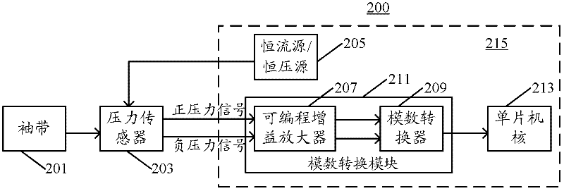
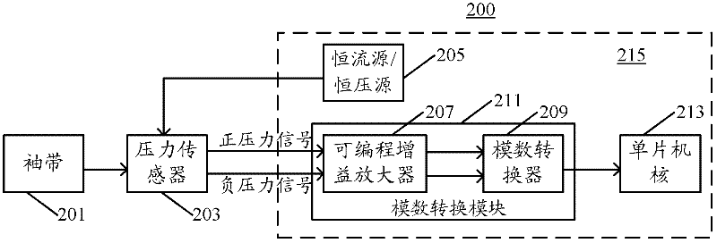
[0038] figure 2 It is a schematic diagram of a highly integrated electronic sphygmomanometer circuit according to an embodiment of the present invention. As shown in the figure, the electronic sphygmomanometer circuit 200 may include: a pressure sensor 203 , a constant current source / constant voltage source 205 , an analog-to-digital conversion module 211 and a single-...


PUM


Abstract

The invention provides a highly integrated electronic sphygmomanometer circuit, which comprises a pressure sensor, a constant current source / constant voltage source, a programmable gain amplifier, an analog-to-digital converter and a single-chip core, wherein the pressure sensor is used for receiving a human body blood pressure signal; the constant current source / constant voltage source is used for providing a constant current / voltage to the pressure sensor; the programmable gain amplifier is used for receiving a differential input positive and negative pressure signal of the pressure sensor and adjusting to required gain amplification; the analog-to-digital converter is used for performing analog-to-digital conversion on the positive and negative pressure signal after the gain amplification; the single-chip core is used for controlling the entire electronic sphygmomanometer circuit to perform data operation, processing or interruption; and the constant current source / constant voltage source, the programmable gain amplifier, the analog-to-digital converter and the single-chip core are integrated on a chip. The circuit is highly integrated, and a fully differential input analog-to-digital conversion module is built in the chip, so that the number of peripheral separation components can be reduced and the accuracy of a measured signal is improved.

Description

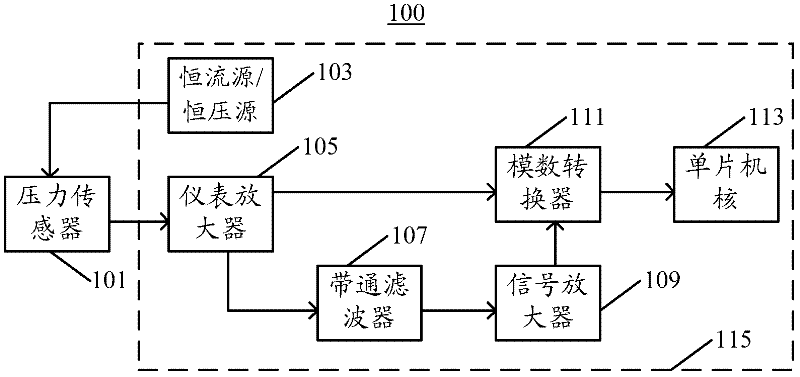
technical field [0001] The invention relates to the technical field of single-chip microcomputer circuits, in particular, the invention relates to a highly integrated electronic sphygmomanometer circuit. Background technique [0002] The vast majority of non-invasive electronic sphygmomanometers or blood pressure monitors use the oscillometric method. figure 1 It is a schematic diagram of an electronic sphygmomanometer circuit in the prior art. As shown in the figure, the electronic sphygmomanometer circuit 100 may include: [0003] The pressure sensor 101 is used to receive the blood pressure signal of the human body; [0004] A constant current source / constant voltage source 103, connected to the pressure sensor, for providing constant current / voltage to the pressure sensor; [0005] The instrument amplifier 105 is connected with the pressure sensor and is used to amplify the pressure signal output by the pressure sensor; [0006] A bandpass filter 107 is connected with...

Claims


Application Information

Patent Timeline
Patent Type & Authority Applications(China)
IPC IPC(8): A61B5/0225
Inventor 曹中信许成珅
Owner SINO WEALTH ELECTRONICS
Learn More