Crowned tooth gear, processing method and processing milling cutter

A crown-shaped tooth and gear technology, which is applied in the field of mechanical parts and gears, can solve the problems of affecting the service life of the coupling, increasing contact stress, and deterioration of the contact between the crown-shaped gear teeth and the ring gear, etc., and achieves simple structure, simple processing, The effect of improving performance and service life

Inactive Publication Date: 2012-06-20
YIYANG KANGYI MACHINERY DEV
View PDF0 Cites 16 Cited by
  • Summary
  • Abstract
  • Description
  • Claims
  • Application Information

AI Technical Summary

Problems solved by technology

During use, as the input and output axes change, the position of the used tooth involute is also changing, which leads to the deterioration of the contact between the crown gear teeth and the ring gear, from line contact to point contact, making the contact Increased stress, seriously affecting the service life of the coupling

Method used


Image

  • Crowned tooth gear, processing method and processing milling cutter
  • Crowned tooth gear, processing method and processing milling cutter
  • Crowned tooth gear, processing method and processing milling cutter

Examples


Embodiment 1

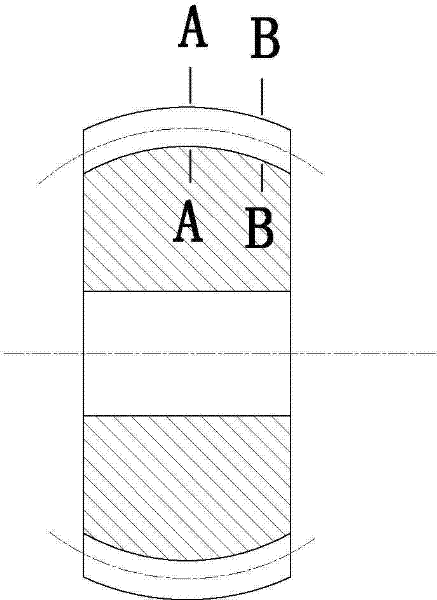
[0040] Depend on Figure 7 It can be seen that a drum-shaped gear is an involute gear, the outer circle of the tooth part is spherical, the tooth shape of the drum-shaped gear 14 is a gradual tooth shape, and the gear teeth have 14 teeth. The long direction is drum-shaped, the tooth profile of the radial section of the gear teeth 14 is consistent, the tooth root is a full arc, and the tooth profile angle is the normal tooth profile angle.

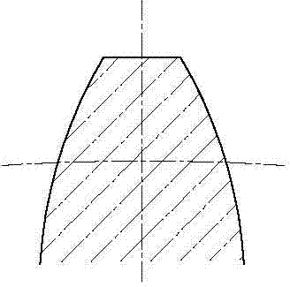
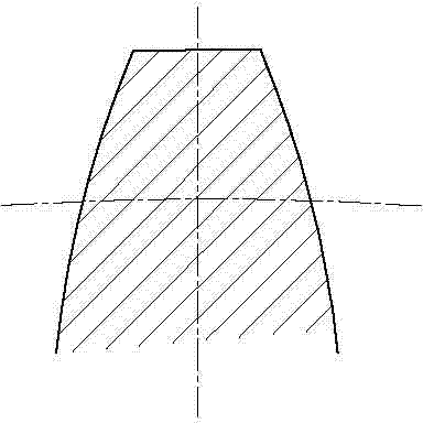
[0041] Depend on Figure 8 , Figure 9 , Figure 10 It can be seen that, since the tooth shape of the drum gear tooth 14 at the maximum drum shape is the same as that deviated from the drum gear tooth 14 maximum drum shape, that is, the tooth shape of the drum gear tooth 14 radial section is the same, the wheel The tooth 14 is in good contact with the tooth shape of the ring gear at any position.

[0042] A method for processing crown-shaped gears as described above, adopts a forming method to process the tooth shape, and it includes th...

Embodiment 2

[0056] Depend on Figure 13 It can be seen that the milling cutter described in this embodiment adopts a finger-shaped milling cutter, and the involute segment 10 of the cutting edge is determined by calculating its coordinate value using gear parameters, and the relational formula is:

[0057] x g =R x sin ω x

[0058] Y g =R x cos ω x

[0059] Where: R x is the radius of any circle of the gear, ω x is the center half angle between the teeth

[0060] ω x =(π-4ξtgα) / 2Z+Δ s / mZ+(invα x -invα)

[0061] Where: ξ is the gear variation coefficient, Δ s is the thinning amount α of the tooth thickness of the gear indexing circle x is the arbitrary circular pressure angle of the gear, α is the graduated circle pressure angle of the gear, Z is the number of teeth of the gear, and m is the modulus of the gear.

[0062] During processing, the milling cutter walks a circular trajectory in the direction of the tooth direction, and the remainder is the same as in embodiment...


PUM


Abstract

The invention discloses a crowned tooth gear. The teeth of the gear are in the form of a gradual tooth profile angle. The gear is characterized in that: the teeth (14) of the crowned tooth gear are in the form of a gradual tooth profile angle; the tooth length direction of the teeth (14) is crowned; the tooth forms of the radial section of the teeth (14) are consistent; and the tooth roots are fully arcs. A processing method of the crowned tooth gear comprises a step of processing the tooth forms by a forming process. The teeth are processed one by one on a numerically controlled milling machine. A used milling cutter comprises a cutter body (8) and a cutter head (9). The shape of a cutting blade of the cutter head (9) is the same as that of tooth slots (13) on the biggest part of the crowned tooth gear in size. The cutting blade comprises an involute section (10) and an arc section (12). The top end of the cutting blade is in full arc smooth connection. The crowned tooth gear is simple in structure, is convenient to process, is applied to a gear coupler, can ensure good linear contact between the crowned tooth gear and a gear ring and no point contact between the crowned tooth gear, ensures the bending strength of the gear roots at the same time, improves the using performance of the gear coupler and prolongs the service life of the gear coupler.

Description

technical field [0001] The invention relates to a mechanical part gear, in particular to a crown-shaped gear, in particular to a crown-shaped gear, a processing method and a milling cutter for processing. Background technique [0002] In mechanical transmission, in order to improve the problem of transmission stability caused by the different shafts of the input and output ends, variable-angle couplings (that is, drum-shaped gear couplings) are usually used in engineering. At present, the processing of drum-shaped teeth is generally completed by CNC hobbing or mechanical lever dragging to form a drum shape in the tooth length direction, and the tooth shape along the tooth length direction is formed by a group of gradual involutes. During use, as the input and output axes change, the position of the used tooth involute is also changing, which leads to the deterioration of the contact between the crown gear teeth and the ring gear, from line contact to point contact, making th...

Claims


Application Information

Patent Timeline
Patent Type & Authority Applications(China)
IPC IPC(8): F16H55/17B23F9/08B23F21/12
Inventor 贺国安樊健康
Owner YIYANG KANGYI MACHINERY DEV
Why Eureka
Try Eureka