
Pipeline detection method and device through exciting axial guided waves by utilizing annular laser

A technology for pipeline detection and excitation axis, which is applied in the direction of optical testing for flaws/defects, etc. It can solve the problems that restrict the application and development of pipeline guided wave detection, the huge laser ultrasonic detection system, and the high requirements for the detection environment, so as to achieve small dispersion and low cost. Low, clear signal effect

Active Publication Date: 2012-06-20
JIANGSU UNIV
View PDF11 Cites 12 Cited by
  • Summary
  • Abstract
  • Description
  • Claims
  • Application Information

AI Technical Summary

Problems solved by technology

[0004] The laser ultrasonic testing system is huge, expensive, technically complex, and has high requirements for the testing environment, which restricts its application and development in pipeline guided wave testing

Method used


Image

  • Pipeline detection method and device through exciting axial guided waves by utilizing annular laser
  • Pipeline detection method and device through exciting axial guided waves by utilizing annular laser
  • Pipeline detection method and device through exciting axial guided waves by utilizing annular laser

Examples


Embodiment Construction

[0023] specific implementation plan

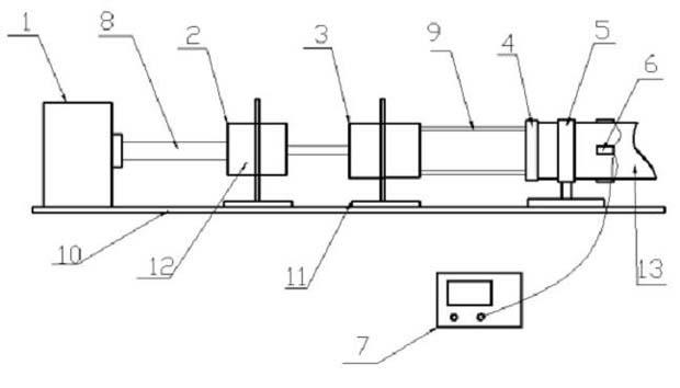
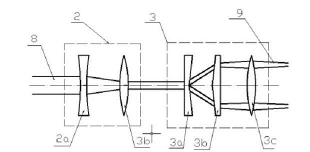
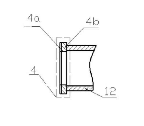
[0024] Such as figure 1 As shown, the device for guiding the axial mode wave in the axial mode of the annular laser excitation pipe has an optical bench 10 for installing and fixing various components, and the horizontal platform of the optical bench 10 is arranged in turn from left to right. The various components of the device 1, the focusing beam reduction optical path system 2, the ring light optical path system 3 and the clamping device 5 can be adjusted and fixed by the mounting bracket 11, and the clamping device is installed at a distance of 1 to 10 cm from the end surface of the pipe position. The pipe 13 to be inspected is placed near the focus point on the right side of the device of the ring light optical system 3 and is center aligned, and the position can be adjusted according to the radius of the pipe to be inspected. The focusing beam reduction optical path system 2 and the ring light optical path system 3 are installed a...


PUM

PropertyMeasurementUnit
thicknessaaaaaaaaaa

Abstract

The invention discloses a pipeline detection method and device through exciting axial guided waves by utilizing annular laser. The pipeline detection method comprises the steps of: converting a round laser beam into an annular laser beam; adjusting the size of the radius of the annular laser beam to enable the radius to be in consistence with the radius of the annular end face of a pipeline; when the annular laser is projected on the annular end face of the pipeline, exciting guided waves in an axial symmetrical mode by generated impact load; and receiving echo signals which are generated when the guided waves meet with a defect by a signal reception device so that detection for a pipeline defect is realized. The pipeline detection method and device through exciting axial guided waves by utilizing the annular laser is good for exciting guided waves in the axial symmetrical mode of the pipeline; as a conical lens group is utilized to collect round flare energy on the annular end face of the pipeline, the effect of the applied impact load is enhanced and SNR (Signal to Noise Ratio) is increased; and as the size of the radius of the annular laser beam is controlled through adjustment of a relative position between the lens group and the end face of the pipeline to adapt to the detection of pipelines with different radiuses, the pipeline detection method and device through exciting axial guided waves by utilizing the annular laser, disclosed by the invention, has the advantages of high efficiency, wide range, relatively low cost and the like.

Description

technical field [0001] The invention relates to a pipeline detection method and device using guided wave, in particular to a pipeline detection method and device using annular laser to excite axial waveguide, which is used for non-destructive detection of pipelines. technical background [0002] In the pipeline guided wave detection, the sensor is an important part of the detection system, which excites and receives the guided wave during the detection process. Whether the ultrasonic guided wave can be effectively excited and received in the tunnel is not only closely related to the characteristics of the guided wave, the size of the pipe, and the environment. Moreover, it is related to the selection and performance of the ultrasonic guided wave probe, and one or more guided waves of different modes that can be excited by different sensors are used to detect the pipeline. At present, the main sensors used to excite guided waves in pipelines include piezoelectric sensors, ma...

Claims


Application Information

Patent Timeline
Patent Type & Authority Applications(China)
IPC IPC(8): G01N21/88
Inventor 姜银方郭镇宁姜文帆张永康黄宇龙昆井然
Owner JIANGSU UNIV
Learn More