
Hydraulic control system for novel servo pump control bending machine

A technology of hydraulic control system and servo pump, which is applied to fluid pressure actuating system components, mechanical equipment, fluid pressure actuating devices, etc. The effect of reducing resistance loss and pressure leakage loss, reducing resistance loss and leakage loss, and reducing system overflow loss

Active Publication Date: 2012-06-27
NANJING ESTUN AUTOMATION CO LTD
View PDF4 Cites 16 Cited by
  • Summary
  • Abstract
  • Description
  • Claims
  • Application Information

AI Technical Summary

Problems solved by technology

The spool valve hydraulic control system equipment developed in the 1950s is mainly used in the CNC bending machine system. The performance parameters of the spool valve hydraulic control system are low. The device produces a large eccentric load moment, which cannot guarantee the displacement accuracy of the oil cylinder, and may cause deformation of the main machine mechanism, resulting in low precision of the bending machine. At the same time, the control part has a complex structure, high failure rate, serious leakage, unstable action, and impact. Big, fast down speed can not be adjusted, takes up a lot of space, and maintenance is inconvenient
[0003] At present, the principle of the hydraulic control system of the domestic electro-hydraulic servo synchronous bending machine is similar. It has not changed for decades. It is a valve control system, which adopts the principle of throttling and speed regulation. The energy loss is large, the system is prone to heat, and the efficiency is low.

Method used


Image

  • Hydraulic control system for novel servo pump control bending machine
  • Hydraulic control system for novel servo pump control bending machine

Examples


Embodiment

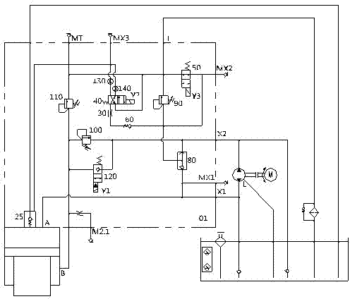
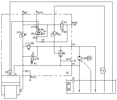
[0013] Embodiment: The connection structure of the control system of this embodiment is as attached figure 1 As shown, it mainly includes the power source and control valve group connected to the numerical control system. Its main feature is that the power source includes a servo motor, a bidirectional quantitative pump connected with the servo motor, and an oil tank; the control valve group includes a pressure valve for adjusting the system pressure. (90), unloading valve (50), also includes shuttle valve (80), check valve (60), reversing valve (40), back pressure valve (100), poppet valve (120), safety valve ( 110) and filling valve (25).

[0014] In this embodiment, the oil inlet and outlet of the two-way quantitative pump are controlled by the shuttle valve (80), the forward oil outlet X1 of the oil pump is directly connected to the upper chamber of the oil cylinder (that is, the rodless chamber A of the oil cylinder), and the reverse oil outlet X2 of the oil pump is The ...


PUM


Abstract

The invention belongs to the technical field of hydraulic control and particularly relates to a hydraulic control system of a novel bending machine, i.e. a servo pump control system. The hydraulic control system comprises a motive power source and a control valve group, wherein the motive power source is connected with a numerical control system. The hydraulic control system is characterized in that the motive power source comprises a servo motor, a bidirectional quantitative pump and an oil tank, the bidirectional quantitative pump and the oil tank are connected with the servo motor, the control valve group comprises a shuttle valve, a pressure valve, an unloading valve, a one-way valve, a reversing valve, a back pressure valve, a poppet valve, a safety valve and a liquid filling valve, the pressure valve is used for regulating the system pressure, an oil inlet and outlet of the bidirectional quantitative pump is controlled by the shuttle valve, a positive oil outlet is directly connected with an upper cavity of an oil cylinder, a reverse oil outlet is connected with a lower cavity of the oil cylinder through the poppet valve and the back pressure valve, an oil inlet and outlet of the bidirectional quantitative pump is connected with the oil tank through the one-way valve, the reversing valve and the liquid filling valve, the liquid charging valve is connected with the control valve, and the safety valve is connected between the oil tank and the lower cavity of the oil cylinder. The hydraulic control system has the characteristics that efficiency is high, the energy is saved, and the synchronous precision is high.

Description

technical field [0001] The invention belongs to the technical field of hydraulic control, and in particular relates to a novel hydraulic control system of a bending machine, that is, a servo pump control system. Background technique [0002] The CNC bending machine is mainly used for sheet metal processing, which can automatically calculate the mechanical position according to the angle, reduce the difficulty of operation and improve work efficiency. The spool valve hydraulic control system equipment developed in the 1950s is mainly used in the CNC bending machine system. The performance parameters of the spool valve hydraulic control system are low. The device produces a large eccentric load moment, which cannot guarantee the displacement accuracy of the oil cylinder, and may cause deformation of the main machine mechanism, resulting in low precision of the bending machine. At the same time, the control part has a complex structure, high failure rate, serious leakage, unsta...

Claims


Application Information

Patent Timeline
IPC IPC(8): B21D5/00F15B21/08
Inventor 余继军柳倩希陈华张党龙
Owner NANJING ESTUN AUTOMATION CO LTD
Learn More