Eureka AIR delivers breakthrough ideas for toughest innovation challenges, trusted by R&D personnel around the world.

Pontoon and water flow power generation combined power station

A combination and pontoon technology, applied in hydroelectric power generation, photovoltaic power generation, wind power generation, etc., can solve the problems of discontinuous power supply, long production off-season, complex control, etc., and achieve the effect of easy installation, maintenance and management, and efficient absorption

Inactive Publication Date: 2014-07-02
庞志森 +4
View PDF7 Cites 0 Cited by
  • Summary
  • Abstract
  • Description
  • Claims
  • Application Information

AI Technical Summary

Problems solved by technology

[0003] In addition, as a general pontoon running water power generation device, it faces many technical difficulties, which makes it difficult to put the general pontoon power generation device into practical use
For example, the seasonal unevenness of flowing water and wind energy leads to discontinuous power supply, long production off-season, low return on investment, and loss outweighing the gain; it is difficult to use low-speed flowing water and low energy efficiency; it is difficult to manage for the majority of non-professional use conditions The control is complicated, and many automatic control systems are imperfect, such as efficiency improvement and stability adjustment according to the unevenness of flowing water flow, power generation quality control, safety protection control, overspeed protection in flood seasons, problems with more floating objects on the water, etc.
The key lies in the lack of practical technology

Method used


Image

  • Pontoon and water flow power generation combined power station
  • Pontoon and water flow power generation combined power station
  • Pontoon and water flow power generation combined power station

Examples


Embodiment Construction

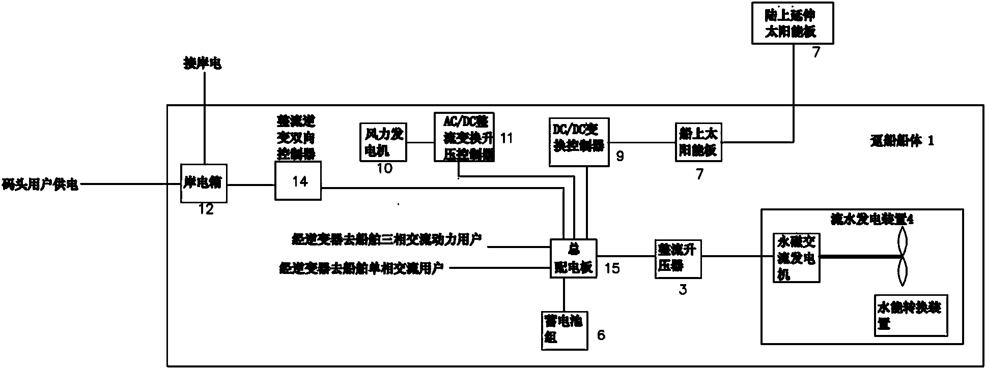
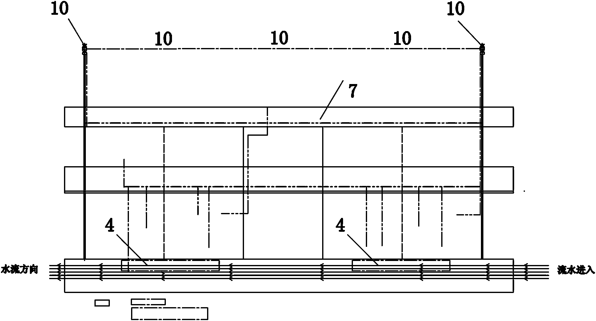
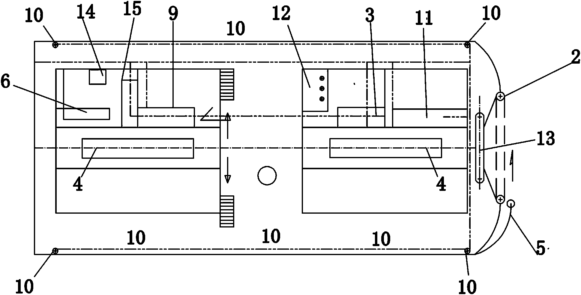
[0046] Such as figure 1 Among them, a barge flowing water power generation combined power station includes a barge 1, and the described barge 1 is provided with a flowing water generating device 4, a solar panel 7 and / or a wind power generating device 10; a flowing water generating device 4, a solar panel 7 and The wind power generation device 10 may be provided with one or more of them according to local conditions. For example, in an area with insufficient wind energy, the installation of the wind power generation device 10 is abandoned, or in an area with insufficient sunlight, the installation of the solar panel 7 is abandoned, so as to improve the overall cost performance of the power station.

[0047] The flowing water power generation device 4 is connected to the main switchboard by cables through the rectifier booster 3; the flowing water power generation device 4 usually adopts a permanent magnet alternator, which is boosted by the rectifier booster 3 and then supplie...


PUM


Abstract

A pontoon and water flow power generation combined power station comprises a pontoon. A belt hydraulic engine type water flow power generation device, a solar power generation device and / or wind driven power generation device are arranged on the pontoon, and the belt hydraulic engine type water flow power generation device is provided with an automatic working water level regulating unit, a super-flood preventing unit and a float cleaning unit. A belt hydraulic power generator, a magnetic suspension wind driven power generator and a solar power generator are assorted mutually and are integrated with the shore supply to realize interaction and compensation, and specifically, power generated from flood and / or wind and solar energy in peak periods is fed back to the shore supply, and the shore supply resupplies power for the pontoon when in off-peak periods of flood and / wind and solar energy, so that uninterrupted power supply is formed, and the multipurpose pontoon with new clean energy self-generating devices is assembled. Besides, automatic control and dispatching of various power supplies can be realized, and accordingly the pontoon and water flow power generation combined power station has the advantages of operational simplicity, safety and reliability, high efficiency, adaptability to non-professional management, and can be used as a composite marine facility with double functions of the pontoon and the power station or can be used as a special shore power station utilizing integral energy.

Description

technical field [0001] The utility model relates to a static marine facility and a multi-functional comprehensive facility for a power station which utilizes clean energy to form an uninterrupted power supply, in particular to a multifunctional comprehensive facility which has the function of a barge and can make full use of low-speed flowing water, wind and light energy. The barge flowing water power generation combined power station for power generation, or a dedicated comprehensive energy power station, can also be called a composite facility of a barge and flowing water combined power station, or a dedicated waterfront comprehensive energy power station. Background technique [0002] Barge is a kind of non-self-propelled ship, which is docked on the shore of the port wharf for mooring and mooring of self-propelled ships. It is used as a working platform and tool for ships to communicate with land, and also a link and bridge connecting ships and land. At present, almost a...

Claims


Application Information

Patent Timeline
Patent Type & Authority Patents(China)
IPC IPC(8): H02S10/10H02S10/12H02K7/18H02J7/00H02J3/32B63B35/34
CPCY02E10/763Y02E10/725Y02E10/20Y02E10/50Y02E10/72Y02E10/76
Inventor 庞志森王文忠庞明黎泽洲
Owner 庞志森
Why Eureka
Eureka Blog
Learn More