Method for transporting energy of gas-liquid two-phase flow

A gas-liquid two-phase flow and energy technology, which is applied in the field of gas-liquid two-phase flow energy transport, low energy consumption and high density energy transport, can solve the problems of difficult to achieve optimal design and complex structure, and achieve large-scale production and high-density energy transport. Large-scale application, reducing heat exchanger area, reducing the effect of irreversible losses

Inactive Publication Date: 2012-06-27
QINGDAO UNIV
View PDF4 Cites 23 Cited by
  • Summary
  • Abstract
  • Description
  • Claims
  • Application Information

AI Technical Summary

Problems solved by technology

[0004] The purpose of the present invention is to overcome the shortcomings of the prior art, seek to design and propose a low-energy-consumption, high-density, high-efficiency energy transport system method that utilizes gas-liquid two-phase flow to transport heat energy from one area to another area, and is easy to real...

Method used


Image

  • Method for transporting energy of gas-liquid two-phase flow
  • Method for transporting energy of gas-liquid two-phase flow
  • Method for transporting energy of gas-liquid two-phase flow

Examples


Embodiment 1

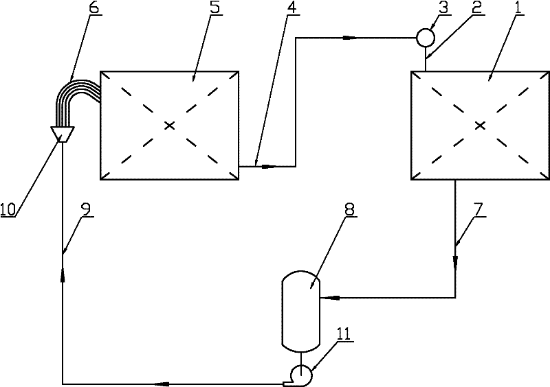
[0021] Example 1: The workflow of the first gas-liquid two-phase flow energy transport is as follows figure 1 As shown, its main components include a first evaporator 5 and a first condenser 1; it also includes a condensate liquid supply and distribution system consisting of a solution circulation pump 11, a solution transport pipe 9, a liquid separator 10 and a uniform liquid pipe 6 Subsystem: gas-liquid two-phase flow and distribution subsystem composed of gas-liquid two-phase flow main pipe 4, two-phase flow distributor 3 and two-phase flow equalizing pipe 2; liquid return main pipe 7, liquid storage tank 8 The liquid phase collection and storage subsystem constituted; the start-up and operation process of its energy transport system device is as follows: firstly, a gas-liquid two-phase flow energy transport system is figure 1 After the installation shown in the figure is completed, fill in an appropriate amount of circulating working medium after evacuation, start the solu...

Embodiment 2

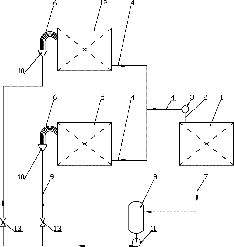
[0022] Example 2: figure 2 It is the work flow diagram of the energy transport of the second gas-liquid two-phase flow, the first condenser 1 and the liquid phase collection and storage subsystem are exactly the same as those in Embodiment 1, but the first evaporator 5 and the condensed liquid supply and The distribution subsystem and gas-liquid two-phase flow are different from the distribution subsystem. In Embodiment 1, there is only one evaporator, but in this embodiment there are more than two evaporators ( figure 2 Only 2 are drawn in ), the condensate liquid supply and distribution subsystem, the gas-liquid two-phase flow and distribution subsystem have multiple channels, and a solution regulating valve is installed on each channel of the condensate liquid supply and distribution subsystem 13. Adjust the flow rate according to the heat load of the corresponding evaporator; apply this embodiment to take heat from multiple heat sources and deliver it to a user, realizin...

Embodiment 3

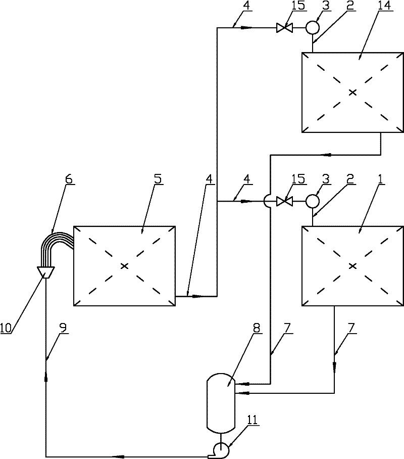
[0024] Example 3: image 3 It is the working flow diagram of the third energy transport method, the first evaporator 5 and the condensate liquid supply and distribution subsystem are basically the same as those in Embodiment 1, the condenser, the gas-liquid two-phase flow and distribution subsystem, the liquid phase Collection is different from storage; there is only one condenser in embodiment 1, and there are more than two condensers in this embodiment ( image 3 Only 2 are drawn in ), the condensate collection and storage, gas-liquid two-phase flow and distribution subsystem has multiple channels, and a two-phase flow regulating valve is installed on each channel of the gas-liquid two-phase flow and distribution subsystem 15. Adjust the flow rate according to the heat load of the corresponding condenser; apply this embodiment to take heat from one heat source and deliver it to multiple users, realizing a heat energy transportation mode of supplying multiple users.

[0025]...


PUM


Abstract

The invention relates to a method for transporting the energy of a gas-liquid two-phase flow and belongs to the technical field of energy transportation. An evaporator and a condenser which are both heat exchangers are respectively arranged at a place supplying cold energy and heat energy and at a place using cold energy and heat energy; the evaporator and the condenser are organically connected into a whole through a gas-liquid two-phase flow main pipe, a two-phase flow distributor, a two-phase flow equalizing pipe, a main liquid return pipe, a liquid storage tank, a cycling solution pump, a solution transport pipe, a liquid separator and a liquid equalizing pipe to form an energy transport system of gas-liquid two-phase flow; heat energy carrying working media from the evaporator to the condenser is in a state of the gas-liquid two-phase flow; heat energy carrying working media from a heating section to a cooling section is in a liquid-phase state; the energy transport system of gas-liquid two-phase flow is different from a heat pipe energy transport system; heat energy carrying working media from the evaporator to the condenser is in a gas-phase state, thus the method for transporting the energy of the gas-liquid two-phase flow is formed; and when the circulation is repeated, the cold energy and the heat energy can be transported continuously. The invention has the advantages of reliable transport principle, simple equipment, high heat efficiency and significant economic and social benefits.

Description

Technical field: [0001] The invention belongs to the technical field of energy transportation, and relates to a low-energy-consumption and high-density energy transportation method using gas-liquid two-phase flow to transport heat energy from one region to another, in particular to a gas-liquid two-phase flow energy transportation method. shipping method. Background technique: [0002] In the actual life and production process of human beings, there are often occasions where heat is transported from one area to another. Such as the utilization of seawater (river or lake) heat energy, there is often a long distance between the location of seawater (river or lake water) and the user who needs its heat energy; another example is the application of soil heat source or groundwater heat source, which can obtain such cooling There is often a long distance between the place where heat energy and heat energy is used and the user; another example is the recycling of cold and heat ene...

Claims


Application Information

Patent Timeline
IPC IPC(8): F28D15/02
Inventor 田小亮刘瑞璟刘春涛王宗伟王兆俊
Owner QINGDAO UNIV
Why Eureka
Try Eureka