Double heat energy heating biogas system

A technology of biogas and thermal energy, which is applied in the field of biogas engineering, can solve the problems of high investment and operation cost, low gas production rate, low cost performance, etc., and achieve the effect of good warming effect, low cost and strong environmental protection

Inactive Publication Date: 2012-07-04
方朝阳
View PDF4 Cites 17 Cited by
  • Summary
  • Abstract
  • Description
  • Claims
  • Application Information

AI Technical Summary

Problems solved by technology

[0008] The purpose of the present invention is to overcome the defects and problems of low concentration, low temperature, low stirring rate, low gas production rate, low energy saving, low cost performance and high investment and operation cos

Method used


Image

  • Double heat energy heating biogas system
  • Double heat energy heating biogas system
  • Double heat energy heating biogas system

Examples


Embodiment 1

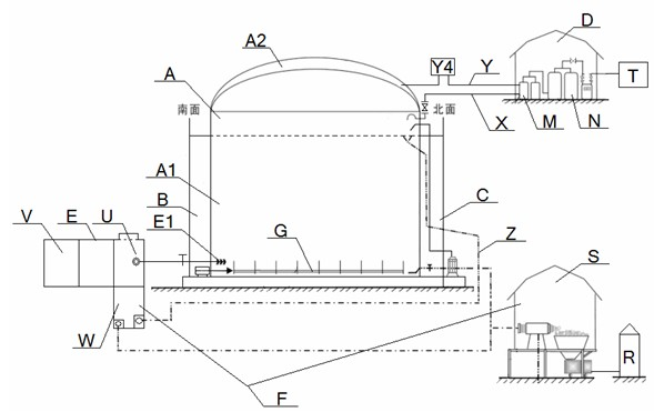
[0149] A biogas system with dual heat energy heating, including a fermenter A, a feeding device E, a biogas purification device D, and a biogas residue treatment device F. A stirring device G is installed inside the fermenter A, and a temperature increasing device is arranged outside the fermenter A. The heating device includes a solar heating device B and an auxiliary thermal heating device C; the feeding device E includes a deployment tank U and at least two sedimentation tanks V, and the biogas purification device D includes a multifunctional automatic regulator M and a purifier N, the biogas residue treatment device F includes a biogas slurry waste heat conduction pool W and a solid-liquid separator S, and the slag outlet of the solid-liquid separator S is connected to the biological fertilizer equipment R;

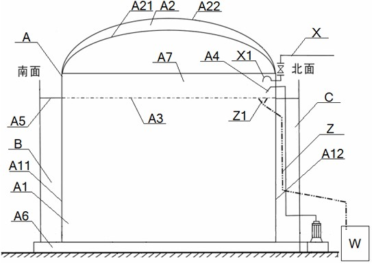
[0150] The fermenter A includes a tank body A1 and an air film A2 provided on its top. The air film A2 includes an inner film A21 and an outer film A22. The inside of ...

Embodiment 2

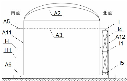
[0169] The basic situation is the same as that of Example 1, the difference is that: the solar heating device B is the No. The solar heating room J is connected with the direct heating room K of the fully enclosed boiler. The width of the direct heating room K of the fully enclosed boiler is 0.6 meters, and the width of the No. 2 solar heating room J is 0.5 meters;

[0170] The No. 2 solar warming room J includes an arc-shaped transparent glass wall H1 and a closed door H2. The transparent glass wall H1 is arranged around the south side wall A11. The two ends of the transparent glass wall H1 are respectively connected to the closed door H2 and the No. The wall K1 is connected, and the top of the transparent glass wall H1 is provided with a platform A5; the fully enclosed boiler direct heating room K includes a curved No. 2 thermal insulation brick wall K1, entry I2 and a fully enclosed safe and energy-saving biogas boiler L , the No. 2 thermal insulation brick wall K1 is arran...


PUM


Abstract

The invention discloses a double heat energy heating biogas system, which comprises a fermentation tank, a feeding device, a biogas purification device and a biogas residue treatment device. A stirrer device and a heating device are arranged in the fermentation tank; the heating device comprises a solar energy heating device and an auxiliary heat energy heating device; the auxiliary heat energy heating device is a bioenergy heating house or a fully enclosed boiler directly-heated type heating house; the feeding device comprises a blending tank and a sedimentation tank; the biogas residue treatment device comprises a biogas slurry afterheat conducting tank and a solid-liquid separator connected with a biological fertilizer making equipment; the side faces of the blending tank are provided with the sedimentation tank, the biogas slurry afterheat conducting tank and a grit chamber; the biogas purification device comprises a multifunctional automatic regulator and a purifier; and the multifunctional automatic regulator comprises a gas-water separator and a positive and negative pressure protector. The system has the advantages of high concentration, high temperature, high stirring rate, high gas production rate, high energy conservation, high cost performance, low tank body, low investment, low danger and low operating cost.

Description

technical field [0001] The present invention relates to a biogas project, in particular to a biogas system with dual thermal energy heating type, which is specifically suitable for realizing the six-high and four-low effects of the biogas project. "Six high" refers to high concentration, high temperature, high stirring rate, and high gas production. High efficiency, high energy saving and high cost performance, "four lows" refer to low tank body, low investment, low risk and low operating cost. Background technique [0002] At present, the large and medium-sized biogas projects in China all adopt the traditional USR or CSTR process, which not only has low concentration (TS 3%–5%), low temperature (10–25°C), and low gas production rate (unit volume production Gas rate is about 0.3–0.5m3 / m3·d), and there are problems such as high energy consumption, low efficiency, and abnormal operation in winter on key equipment, and the benefits of energy saving and emission reduction and c...

Claims


Application Information

Patent Timeline
IPC IPC(8): C12M1/107C12M1/02
CPCY02E50/343C12M41/12C12M43/00C12M21/04C12M27/06Y02E50/30Y02P20/59
Inventor 方朝阳
Owner 方朝阳
Why Eureka
Try Eureka