
Method for reinforcing bridge structure separated steel-concrete combined truss

A technology of bridge structure and combined truss, which is applied in the bridge and structural engineering fields of civil engineering, and can solve the problems of beam surface flatness, high cleanliness requirements, poor durability, and insignificant improvement of FRP reinforced structure stiffness, etc.

Active Publication Date: 2012-07-04
SHUOHUANG RAILWAY DEV +3
View PDF4 Cites 22 Cited by
  • Summary
  • Abstract
  • Description
  • Claims
  • Application Information

AI Technical Summary

Problems solved by technology

[0007] (2) Although the construction process of the bonded steel reinforcement method is relatively simple, it can improve the bearing capacity of the structure to a certain extent, but it has higher requirements on the smoothness and cleanliness of the surface of the beam body, and the effectiveness of the reinforcement mainly depends on the bonding material. Strength and durability, fatigue resistance is not stable enough
[0008] (3) The improvement of structural rigidity by FRP reinforcement is not obvious, the problems of shear resistance and connection are relatively prominent, and the durability and fire resistance of the bonded surface between FRP material and concrete are poor
[0009] To sum up, traditional reinforcement methods have defects such as insufficient connection reliability of old and new materials, limited improved bearing capacity, and poor durability.

Method used


Image

  • Method for reinforcing bridge structure separated steel-concrete combined truss
  • Method for reinforcing bridge structure separated steel-concrete combined truss
  • Method for reinforcing bridge structure separated steel-concrete combined truss

Examples


Embodiment Construction

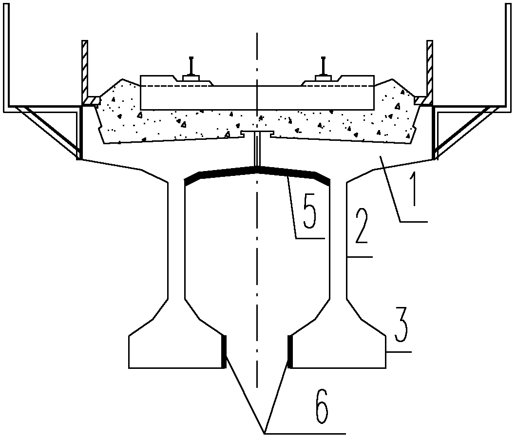
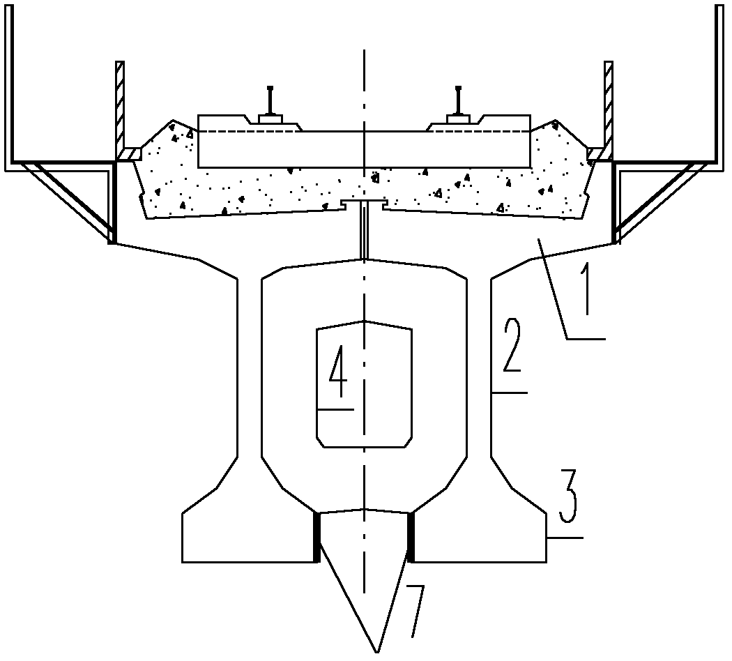
[0133] Preferred embodiments of the present invention are described below in conjunction with accompanying drawings, wherein reference numerals in the figure represent: 1-concrete T-beam top plate; 2-concrete T-beam web; 3-concrete T-beam bottom plate; 4-diaphragm; 5-reinforced interface of upper flange; 6-reinforced interface of lower flange; 7-reinforced interface of lower flange of diaphragm; 8-planted reinforcement; 9-bolt; 10-steel plate; Steel box girder; 13- low-height steel box girder diaphragm; 14- unbonded prestressed steel strand; 15- truss diagonal bar; 16- truss vertical bar; 17- gusset plate; 18- three-sided surrounding welding 19-hole steel plate; 20-through steel bar; 21-upper flange reinforced concrete; 22-lower flange reinforced concrete; 23-fulcrum anchor box; 24-concrete pier; 25-support.

[0134] The solution of the present invention is on the basis of the prior art to provide a rapid reinforcement construction technology of a novel bridge structure, the c...


PUM

PropertyMeasurementUnit
Thicknessaaaaaaaaaa
Bulk densityaaaaaaaaaa
Apparent densityaaaaaaaaaa

Abstract

The invention relates to a method for reinforcing a bridge structure separated steel-concrete combined truss. The method is characterized by comprising the following steps of: 1, processing an interface at the joint of upper and lower flanges of a concrete beam; 2, planting steel bars in concrete at the joint of the upper and lower flanges of the concrete beam; 3, manufacturing steel plates (10),low-height steel box girders (12) and welding studs (9); 4, binding steel bar meshes (11), and installing in place; 5, manufacturing and installing upper and lower chord node plates (17) and connecting members thereof; and coating a structural adhesive on pouring joint surfaces of the steel plates (10) and the low-height steel box girders (12), and scattering fine sand; 6, installing the steel plates (10) and the low-height steel box girders (12) of the upper and low flanges, vertical rods (16), an external cable (14) and an anchoring tool; 7, manufacturing and installing truss diagonal web rods (15); 8, constructing a truss support; 9, mixing, spraying and curing self-compacting concrete; and 10, tensioning the external cable (14) to obtain an external prestressed steel-concrete combinedtruss reinforced structure. The method has the advantages that: vehicle operation is not influenced, external prestressed bars can be replaced and repeatedly tensioned, a beam body has superior overall working performance and high durability, the process is simple, the combined truss is convenient to maintain and cure, and the like.

Description

technical field [0001] The invention relates to the field of bridge and structural engineering in civil engineering, in particular to a method for reinforcing and strengthening a bridge superstructure and a construction process, in particular to the rapid strengthening and upgrading of railway bridges. Background technique [0002] For a long time, in order to solve the contradiction between the transportation volume and the insufficient transportation capacity, my country's railway departments have successively adopted methods such as increasing the axle load of trucks, increasing the traffic density, and increasing the train formation to increase the transportation capacity. Unbalanced situation, how to improve transport capacity is still one of the problems to be solved urgently for my country's railways. [0003] Heavy-duty railways have large transportation capacity and significant economic and social benefits. The development of heavy-duty railway transportation has bec...

Claims


Application Information

Patent Timeline
IPC IPC(8): E01D22/00
Inventor 余志武谈遂薛继连李进洲蒋丽忠
Owner SHUOHUANG RAILWAY DEV
Learn More