Cooling water jacket structure of diesel engine cylinder body

A technology for cooling water jackets and cylinder blocks, applied to cylinders, cylinder heads, mechanical equipment, etc. Problems such as temperature unevenness, achieve the effect of reducing particle emission value, simple structure, and enhancing cooling effect

Inactive Publication Date: 2012-07-04
JIANGSU SIDA POWER MECHANICAL GROUP
View PDF8 Cites 11 Cited by
  • Summary
  • Abstract
  • Description
  • Claims
  • Application Information

AI Technical Summary

Problems solved by technology

This structure does not consider the two-way flow around the water jackets of each cylinder block. The design of a single water inlet will inevitably increase the water flow velocity of the cylinder block water jacket on the exhaust side, while the water flow velocity on the intake side slows down, and the cooling water passing through The water temperature is high and the water volume is small, which causes the local temperature of the cylinder block to be uneven, resulting in thermal deformation, and the roughening or pulling of the cylinder liner
In addition, the axial positioning of the wet cylinder liner of the diesel engine adopts the annular support shoulder, and the support shoulder is thick, and the cooling water jacket cannot extend to the position of the first ring of the piston, which seriously affects the cooling of the first piston ring and the upper part of the cylinder liner. Heat dissipation can easily cause cylinder scuffing and affect the reliability of the whole machine

Method used


Image

  • Cooling water jacket structure of diesel engine cylinder body
  • Cooling water jacket structure of diesel engine cylinder body
  • Cooling water jacket structure of diesel engine cylinder body

Examples


Embodiment Construction

[0023] The present invention will be further described below in conjunction with specific drawings and embodiments.

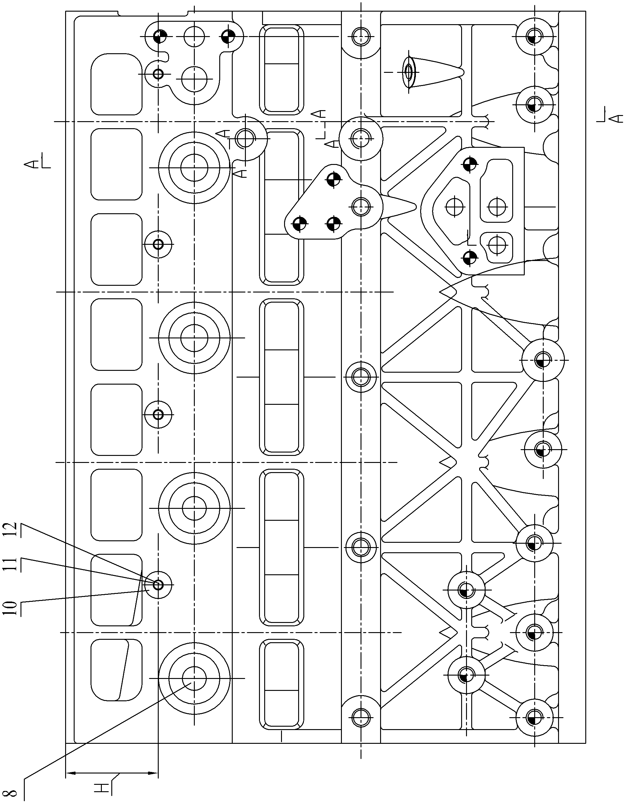
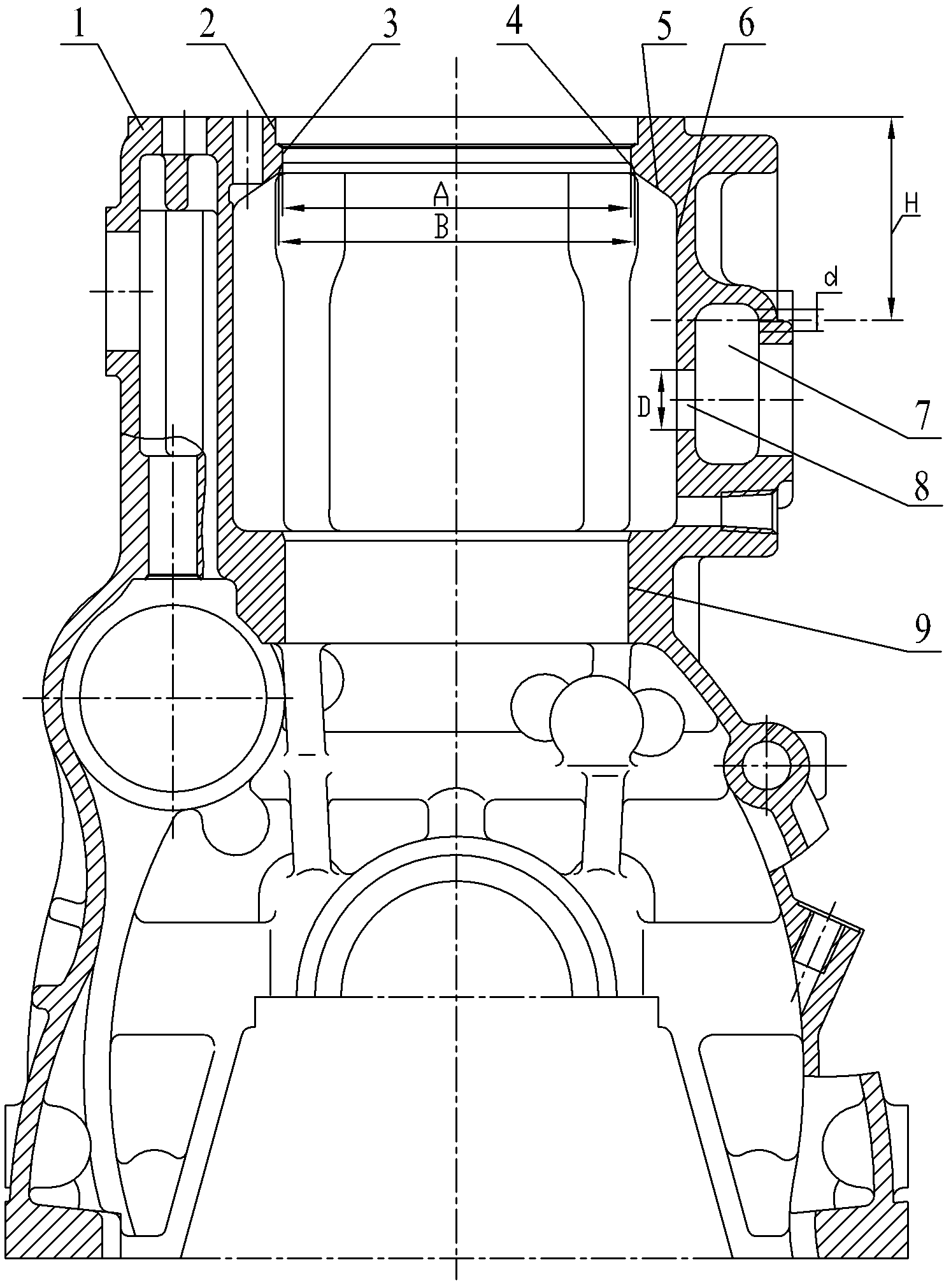
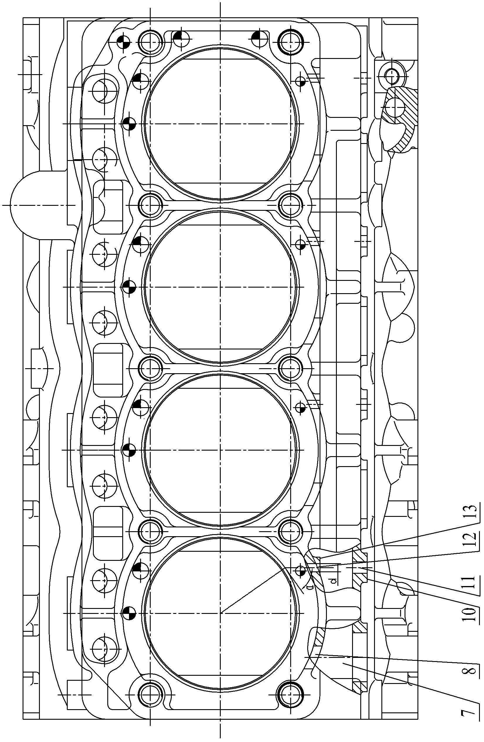
[0024] Such as Figure 1~Figure 5 As shown, the upper part of the intake side of the cylinder block 1 is provided with a transverse water inlet 7, and one end of the water inlet 7 is connected to a water pump; the middle and upper parts of each cylinder of the cylinder block 1 are formed with a cylinder block water jacket 6, and the cylinder block water The sleeve 6 is provided with a water inlet 8 and a drain hole. The water inlet 8 is located on the intake side of the cylinder block 1, and the water inlet 7 communicates with the inside of the cylinder block water jacket 6 through the water inlet 8; A conical cooling water jacket 4 is arranged at the top of the body water jacket 6 extending upward. The conical cooling water jacket 4 is located under the axial positioning annular support shoulder 3 of each cylinder of the cylinder block 1. The conical cooling wate...


PUM


Abstract

The invention relates to a cooling water jacket structure of a diesel engine cylinder body. A water inlet channel is disposed at the upper portion of the air inlet side of the cylinder body, a cylinder body water jacket is formed at the middle upper portion of each cylinder of the cylinder body, and the water inlet channel is communicated with the insides of the cylinder body water jackets through water inlet holes. The diesel engine cylinder body cooling water jacket structure is characterized in that the top ends of the cylinder body water jackets upwards extend to be provided with conical cooling water jackets, the conical cooling water jackets are located below cylinder jacket axial location ring support shoulders of cylinders of the cylinder body, the upper ends of the conical cooling water jackets are connected with the cylinder jacket axial location ring support shoulders, and the lower ends of the conical cooling water jackets are connected with water jacket inner cavity inclined planes of the cylinder body water jackets. The height of each conical cooling water jacket should ensure that when a piston is located at a top dead center, the upper ends of the conical cooling water jackets basically align to the top edge of a first piston ring on the piston. The cooling water jacket structure of the diesel engine cylinder body can ensure that when the piston is located at the compression top dead center, the piston, the piston ring and the cylinder jacket can all be cooled effectively, and scuffing of cylinder bore of the cylinder jacket can be prevented.

Description

technical field [0001] The invention relates to an improvement of a diesel engine component, in particular to a cooling water jacket structure for a 480Z and 480ZL series diesel engine cylinder block, which belongs to the technical field of mechanical structures. Background technique [0002] During the working process of the internal combustion engine, due to the heat released by the combustion of high-temperature gas, the heat load of the heated parts is very high. In order to ensure that these heated components can work normally, it is very important to solve the heat transfer problem of the heated components. For the key parts heated - cylinder liner, piston and piston ring, the reasonable arrangement and design of the cooling water jacket structure, as well as the effective organization of the reasonable flow and distribution of the cooling medium, can effectively solve the heat dissipation problem of the heat-loaded parts . [0003] The structure of the cooling water...

Claims


Application Information

Patent Timeline
Patent Type & Authority Applications(China)
IPC IPC(8): F02F1/16
Inventor 龚灵辉沈新峰陈月生黄敏勤丁剑
Owner JIANGSU SIDA POWER MECHANICAL GROUP
Why Eureka
Try Eureka