
Shell-and-tube heat exchanger with combined type one-shell-pass continuous spiral baffles

A shell-and-tube heat exchanger and helical baffle technology, applied in the direction of heat exchanger type, heat exchanger shell, indirect heat exchanger, etc. Reduce heat transfer efficiency and other issues to achieve the effect of improving overall heat transfer performance, improving surface heat transfer coefficient, and increasing fluid mass flow

Active Publication Date: 2012-07-04
XI AN JIAOTONG UNIV
View PDF9 Cites 50 Cited by
  • Summary
  • Abstract
  • Description
  • Claims
  • Application Information

AI Technical Summary

Problems solved by technology

[0003] The traditional single-bow baffle is widely used due to its simple processing and convenient installation, but there are many problems: ①The single-bow baffle makes the fluid vertically impact the wall of the shell, causing a large pressure drop along the way and increasing the load of power equipment; ②Flow stagnation dead zone occurs at the junction between the baffle plate and the shell wall, resulting in a wide distribution of the residence time of the fluid, which reduces the heat transfer efficiency and is easy to scale; ③The gap between the baffle plate and the shell wall and the deflection There is a leakage flow between the flow plate and the heat exchange tube bundle, which causes a large bypass flow on the shell side. The leakage flow and bypass flow reduce the effective mass flow across the tube bundle and reduce the heat exchange efficiency; ④The fluid with high velocity Sweeping the heat exchange tube bundle will induce the vibration of the tube bundle and shorten the life of the heat exchanger
The combined multi-shell-pass spiral baffle heat exchanger (see patent 200610041949.1) divides the shell side into multiple shell passes, and the fluid passes through each shell pass in series. The pressure loss is greatly increased due to the turning point, and the manufacturing and assembly process is complicated due to the need to insert the cylindrical splitter in the shell side
Parallel combined multi-shell-pass spiral baffle shell-and-tube heat exchanger (see patent 200910021347.3) uses deflectors and cylindrical dividers to divide the shell side into parallel two-shell or multi-shell heat exchangers, although it can Reduce shell side pressure loss, but there is uneven flow distribution of different shell side fluids, which may lead to insufficient flow of a certain shell side fluid, affecting the overall heat transfer performance of the heat exchanger
Helical baffle heat exchanger with complex flow field and its drag reduction and enhanced heat transfer method (see patent 200610033075.5) utilizes the diversion effect of the inner and outer spiral baffle structures to improve the flow of fluid near the inner wall of the shell and the leeward side of the baffle The flow state of the shell strengthens the mixing between the center of the shell and the peripheral area of ​​the center, but the inner and outer baffles are made of overlapping fan-shaped blocks, and there is still a triangular leakage area at the overlap of the two baffles. There is still a short circuit in the axis area of ​​the heat exchanger shell, resulting in a spiral "zigzag" flow, which affects the performance of the heat exchanger
The shell-and-tube heat exchanger with combined spiral baffles (see patent 200710017395.6) adopts discontinuous spiral baffles in the central area, and each inner spiral baffle is close to the inner helix of the outer spiral baffle, and the inner and outer baffles The strict matching relationship of the plates makes assembly difficult, and at the same time, there is still a triangular leakage area in the inner helix, and there is a short circuit in the axis area of ​​the shell
[0007] In the shell-and-tube heat exchanger, there is still a large gap between the outermost tube bundle and the inner wall of the shell, where the bypass flow seriously reduces the effective mass flow rate of the fluid across the tube bundle and reduces the heat exchange efficiency
[0008] In addition, the general industrial shell-and-tube heat exchangers are mostly horizontal, which often has the problem of fouling, especially when the flow rate on the shell side is low and the fluid is a medium that is prone to fouling, a large amount of dirt is deposited on the bottom of the heat exchanger and cannot be removed , which seriously affects the heat transfer efficiency

Method used


Image

  • Shell-and-tube heat exchanger with combined type one-shell-pass continuous spiral baffles
  • Shell-and-tube heat exchanger with combined type one-shell-pass continuous spiral baffles
  • Shell-and-tube heat exchanger with combined type one-shell-pass continuous spiral baffles

Examples


Embodiment Construction

[0048] The present invention will be described in detail below in conjunction with the accompanying drawings and specific embodiments.

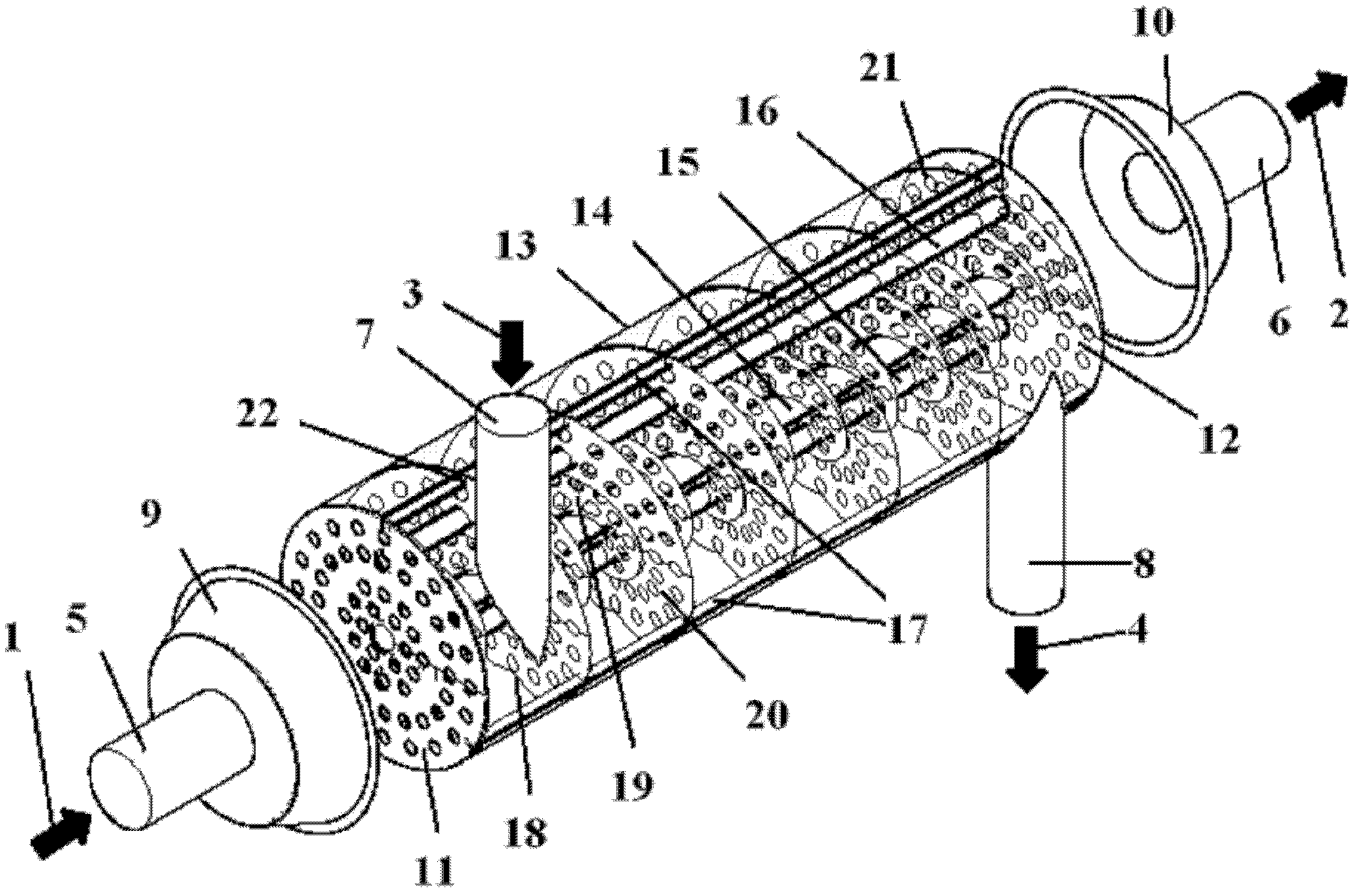
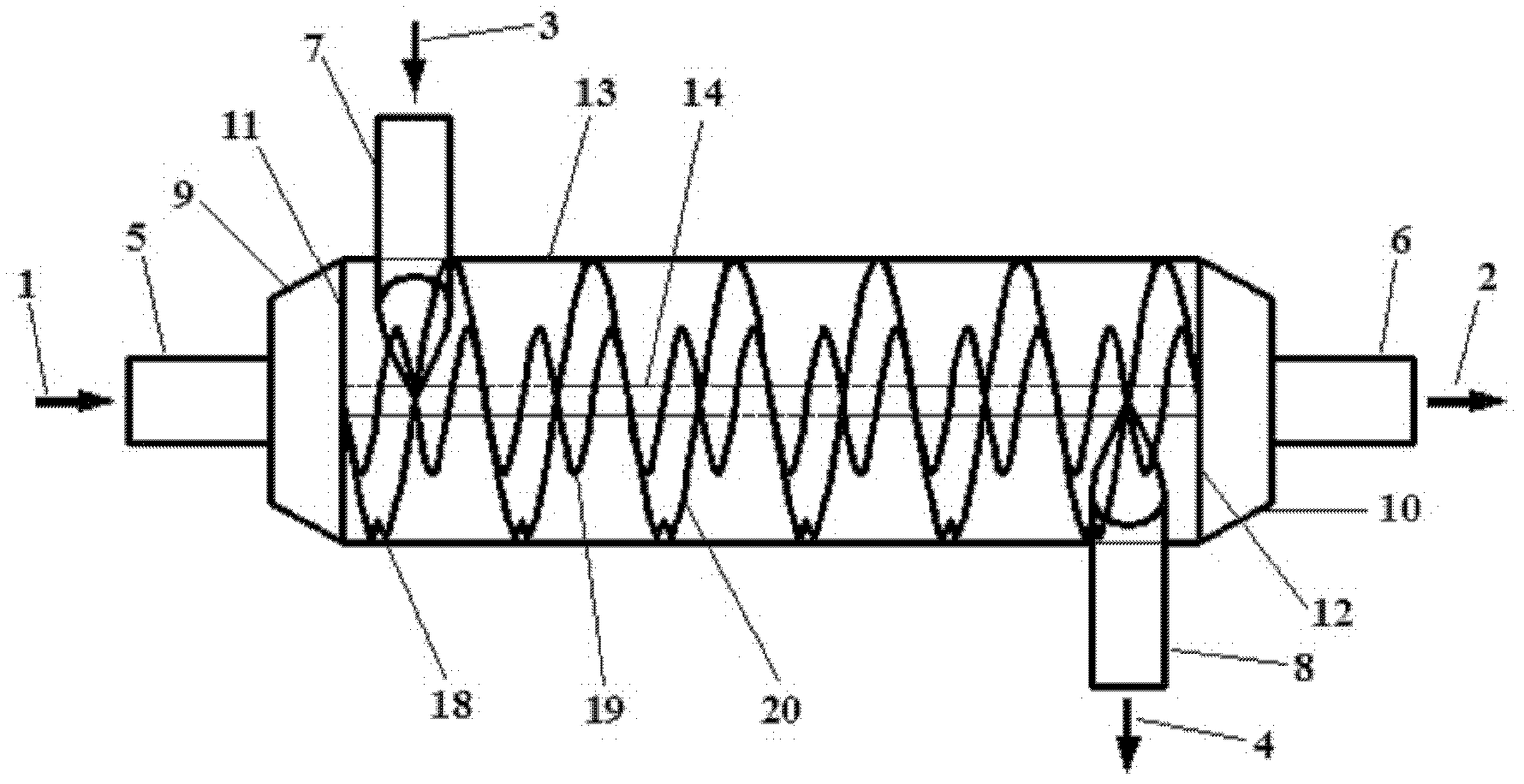
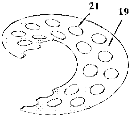
[0049] Referring to Fig. 1 (a, b), a combined single-shell pass continuous spiral baffle shell-and-tube heat exchanger includes: a shell 13, a central tube 14 located in the center of the shell 13, and a central tube 14 located in the shell The tube sheet 11 and the tube sheet 12 at both ends of the body 13, the tube sheet 11 is connected to the first head 9, and the tube sheet 12 is connected to the second head 10, wherein the first head is provided with a tube-side inlet pipe 5, and the second head A pipe-side outlet pipe 6 is provided on it. Between the two tube sheets 11 and 12, there are heat exchange tube bundles 15 (there are many, and only a representative one is shown in Fig. , 20), fixed distance belt 17 (mainly plays the role of fixing outer spiral baffle 20 and reducing side flow) and spiral baffle, and the spiral baffle is provi...


PUM


Abstract

The invention relates to a shell-and-tube heat exchanger with combined type one-shell-pass continuous spiral baffles. The heat exchanger comprises a shell, a central tube, tube plates, a tube-side inlet tube, a tube-side outlet tube, a heat exchange tube bundle, a distance-setting tube, a distance-setting belt, a shell-side inlet tube and a shell-side outlet tube; and the spiral baffles comprise inner continuous spiral baffles and outer continuous spiral baffles. The heat exchange is characterized in that by utilization of different flow guiding actions of the inner continuous spiral baffles and the outer continuous spiral baffles, since cylinder partitioning plates are not arranged between the inner continuous spiral baffles and the outer continuous spiral baffles, the mixing of fluids at the center of the shell and the peripheral area of the center of the shell is enhanced, the flow state at the follow-wind side of the baffles is improved, the turbulent degree of the fluid in the heat exchanger is improved, and the shell-pass heat transfer is enhanced. The shell-and-tube heat exchanger has the advantages that the heat exchange efficiency of the heat exchanger is improved, the pressure loss is reduced, the bottleneck for limiting the heat exchanger with the spiral baffles to the large-flow operation is broken through, simultaneously, the structure is simple, the compactness is high, the vibration when the heat exchanger is operated is reduced, the scaling is not easy, the safety of the heat exchanger is improved and the service life is prolonged.

Description

technical field [0001] The invention relates to a shell-and-tube heat exchanger used in petrochemical, energy, electric power, metallurgy, refrigeration, seawater desalination and other industries, in particular to a combined single-shell continuous spiral baffle shell-and-tube heat exchanger device. Background technique [0002] Shell and tube heat exchanger is an important unit equipment widely used in petrochemical, energy, electric power, metallurgy, refrigeration, seawater desalination and other industrial fields. Due to the mature manufacturing process and high safety, it occupies the largest proportion in heat exchange equipment, especially in harsh occasions such as high temperature, high pressure, and toxicity, tube and tube heat exchange equipment has great advantages. In a shell-and-tube heat exchanger, two fluids, hot and cold, flow in the tube, and the other fluid flows in the shell side, and exchange heat through the heat exchange tube wall. In order to meet ...

Claims


Application Information

Patent Timeline
IPC IPC(8): F28F9/24
CPCF28D7/16F28F9/0131F28F2009/228F28F9/24F28F9/22
Inventor 王秋旺杨建锋陈贵冬曾敏
Owner XI AN JIAOTONG UNIV
Learn More