Digital-shaft angle signal converting method

A signal conversion and digital signal technology, applied in the direction of digital-to-analog converters, transmission of sensing components using electromagnetic/magnetic devices, etc., can solve the problems of single function, low product cost performance, poor adaptability, etc., and achieve high conversion accuracy and scalability. strong effect

Active Publication Date: 2012-07-04
连云港杰瑞电子有限公司
View PDF5 Cites 11 Cited by
  • Summary
  • Abstract
  • Description
  • Claims
  • Application Information

AI Technical Summary

Problems solved by technology

Existing digital-axis-angle converters can only convert one signal type, one signal voltage, and one signal frequency, and have a single function; although the axis-angle simulator can realize programmable frequency, voltage, and s

Method used


Image

  • Digital-shaft angle signal converting method
  • Digital-shaft angle signal converting method
  • Digital-shaft angle signal converting method

Examples


Embodiment example 1

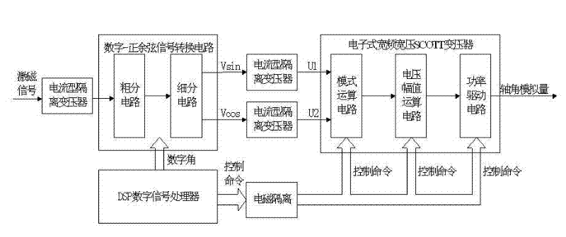
[0024] Implementation case 1, refer to Figure 1-4 , a digital-axis angle signal conversion method, the circuit for realizing the method includes a digital-sincosine signal conversion circuit, an electronic wide-bandwidth wide-voltage SCOTT transformer and a DSP digital signal processor;

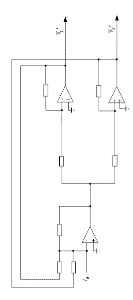
[0025] The digital-sincosine signal conversion circuit is composed of a subdivision circuit and a rough division circuit; the subdivision circuit is a low 16-bit weight resistance network D / A conversion circuit, and the rough division circuit is composed of a precision resistance network, a precision operational amplifier and an analog switch; The electronic wide-band wide-voltage SCOTT transformer is composed of a mode operation circuit, a voltage amplitude operation circuit and a power drive circuit;

[0026] The digital-sincosine signal conversion circuit receives the external input excitation signal isolated by the current-type transformer and the 20-bit digital angle θ sent by the DSP d...

Embodiment 2

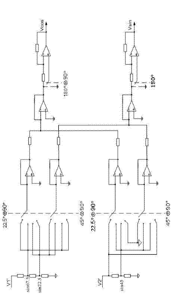
[0027] Embodiment 2, in the digital-axis angle signal conversion method described in Embodiment 1: the digital-sin-cosine signal conversion circuit is realized by a high 4-bit coarse weighted resistance network and a low 16-bit subdivision weighted resistance network, and the weighted resistance network is equal to Adopt low-temperature drift precision resistance network architecture, high 4-bit rough angle and low 16-bit subdivision angle are synthesized into 20-bit full angle according to trigonometric function positive and cosine angle sum and difference digital expression; realize 0.001° precision 2V low voltage positive Cosine signal output.

Embodiment 3

[0028] Embodiment 3, in the digital-axis angle signal conversion method described in Embodiment 1: the mode operation circuit is composed of a precision resistor, a precision operational amplifier and a front-end input relay, and receives two fixed sine and cosine signals: According to different output signal modes, switch the corresponding circuit; when the four-wire resolver signal is output, the SGND, cosθ, sinθ and CGND signals are amplified and then output to the voltage amplitude calculation circuit; when the three-wire auto-synchronizer signal is output, SGND , -sin(θ+240°) and sinθ signals are amplified and output to the voltage amplitude operation circuit.


PUM


Abstract

The invention provides a digital-shaft angle signal converting method. The method is characterized in that: a circuit realizing the method comprises a digital-sine and cosine signal converting circuit, an electronic wide-frequency and wide-voltage SCOTT transformer and a digital signal processor (DSP), wherein the digital-sine and cosine signal converting circuit consists of a subdivision circuit and a rough division circuit; the subdivision circuit is a resistance network digital/analogue (D/A) conversion circuit which is less than 16 bits; the rough division circuit consists of a precise resistance network, a precise operational amplifier and an analogue switch; and the electronic wide-frequency and wide-voltage SCOTT transformer consists of a mode operational circuit, a voltage amplitude value operational circuit and a power driving circuit. Full electronic technology is adopted by the digital-shaft angle signal converting method; a wide-frequency and wide-voltage differential synchro signal or rotary transformer signal can be output; the conversion precision is high; and the expandability is high.

Description

technical field [0001] The invention belongs to the technical field of signal simulation and testing, in particular to a digital-shaft angle signal conversion method. Background technique [0002] Common shaft angle signals include synchro signals and resolver signals. The digital-shaft angle converter converts digital angle signals into synchro signals or resolver signals. It is the core device in modern shaft angle electronic conversion technology. , Widely used in aerospace, aviation, radar, fire control and industrial automation fields. Existing digital-to-axis-angle converters can only convert one signal type, one signal voltage, and one signal frequency, and have a single function; although the axis-angle simulator can realize programmable frequency, voltage, and signal type, it only It can achieve 16-bit resolution and 14-bit precision, and the product has low cost performance and poor adaptability, which is not conducive to popularization and application in the fiel...

Claims


Application Information

Patent Timeline
IPC IPC(8): G01D5/14H03M1/66
Inventor 奚志林李云飞寇志强张明
Owner 连云港杰瑞电子有限公司
Why Eureka
Try Eureka