Coupling-based non-contact temperature measurement system and coupling-based non-contact temperature measurement method

A temperature measurement, non-contact technology, applied in the field of non-contact temperature measurement systems based on coupling, can solve problems such as installation difficulties, potential safety hazards of power equipment, and inability to measure temperature safely, and achieve the effect of low cost and simple circuit

Active Publication Date: 2012-07-04
ZHEJIANG UNIV +1
View PDF4 Cites 38 Cited by
  • Summary
  • Abstract
  • Description
  • Claims
  • Application Information

AI Technical Summary

Problems solved by technology

[0004] However, there are some occasions where neither the commonly used contact temperature measurement technology nor the infrared non-contact temperature measurement method can be used.
For example, the internal core wire temperature measurement of high-voltage power cables, because the core wire is protected by an insulating layer, infrared rays cannot penetrate, so infrared temperature measurement technology cannot be used
And because the cable core wire is at a high potential, it is impossible to directly measure the temperature through the circuit contact method for safety reasons.
However, if the optical fiber temperature measurement method is used, although the problem of electrical isolation is solved, it is very difficult in actual installation.
Therefore, at present, there is no reliable temperature measurement technology and equipment for the temperature measurement of the inner core wire of high-voltage power cables, and it is impossible to deploy some safety measures for related applications according to the temperature, so that the power equipment using high-voltage cables still exists. considerable safety hazard

Method used


Image

  • Coupling-based non-contact temperature measurement system and coupling-based non-contact temperature measurement method
  • Coupling-based non-contact temperature measurement system and coupling-based non-contact temperature measurement method
  • Coupling-based non-contact temperature measurement system and coupling-based non-contact temperature measurement method

Examples


Embodiment Construction

[0040] In order to describe the present invention more specifically, the measuring system and its measuring method of the present invention will be described in detail below in conjunction with the accompanying drawings and specific embodiments.

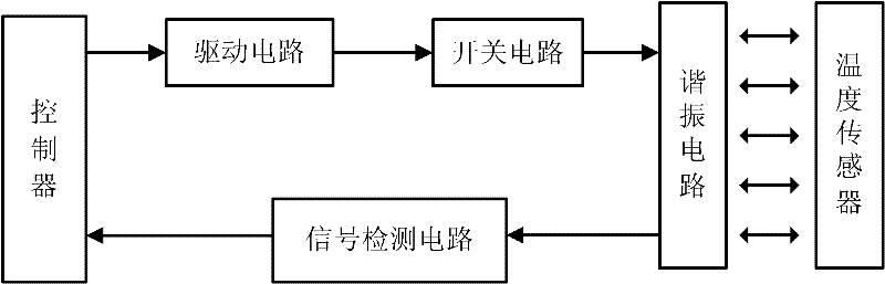
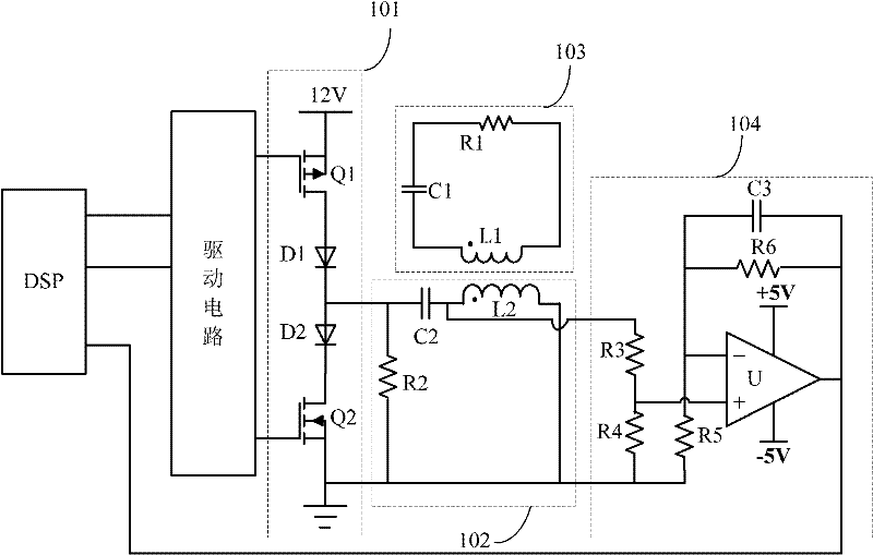
[0041] Such as figure 1 and figure 2 As shown, a coupling-based non-contact temperature measurement system includes: DSP, drive circuit, switch circuit 101 , resonant circuit 102 , signal detection circuit 104 and temperature sensor 103 .

[0042] The driving circuit is connected with the DSP, which amplifies the two driving signals provided by the DSP and then outputs it; in this embodiment, the driving circuit adopts the IRF2110 chip of International Rectifier Company.

[0043] The switch circuit 101 is connected with the drive circuit, and outputs a square wave signal according to the two amplified drive signals provided by the drive circuit; in this embodiment, the switch circuit 101 is composed of two MOS transistors Q1-Q2 and...


PUM


Abstract

The invention discloses a coupling-based non-contact temperature measurement system, which comprises a controller, a drive circuit, a switch circuit, a resonant circuit, a temperature sensor and a signal detection circuit, wherein the drive circuit is connected with the controller, the switch circuit is connected with the drive circuit, the resonant circuit is connected with the switch circuit, the temperature sensor is coupled to the resonant circuit, and the signal detection circuit is connected with the resonant circuit and the controller. The temperature sensor is separated from other devices of the system, non-contact temperature measurement of an object is achieved by electromagnetic coupling, and the system with the simple circuits is low in cost, suitable for miniature design, andapplicable to a plurality of places. The invention further discloses a coupling-based non-contact temperature measurement method, which includes: transmitting temperature signals by electromagnetic coupling, calculating and analyzing according to the temperature signals, and accordingly achieving non-contact temperature measurement of the object. The method is applicable to reliable temperature measurement of inner core wires of a high-tension power cable.

Description

technical field [0001] The invention belongs to the technical field of temperature measurement, and in particular relates to a coupling-based non-contact temperature measurement system and a measurement method thereof. Background technique [0002] In daily life and industrial production process, it is often necessary to measure the temperature of various objects. Temperature is a very important index parameter in many technical fields. In many fields such as industry, medical treatment, military affairs and life, temperature measuring devices are required to monitor temperature. The automatic monitoring of temperature has become one of the important measures for safe production and loss reduction in all walks of life. In certain occasions, due to the scattered and remote monitoring points, the traditional temperature measurement method has a long period and high cost, and the surveyor must go to the site to measure, so the work efficiency is very low. [0003] Temperature...

Claims


Application Information

Patent Timeline
Patent Type & Authority Applications(China)
IPC IPC(8): G01K7/22
CPCG01K7/24G01K7/32G01K7/22G01K7/00
Inventor 吴建德赵崇文何湘宁黄强
Owner ZHEJIANG UNIV
Why Eureka
Try Eureka