
Thermal mechanical fatigue test system for hollow air-cooled turbine blade

A thermo-mechanical fatigue, turbine blade technology, used in the testing of mechanical parts, the testing of machine/structural parts, measuring devices, etc., can solve the problems of nylon wear, large mechanical load, aging, etc., to reduce contact resistance, reliable mechanical load, effect of increasing stability

Active Publication Date: 2012-07-04
BEIHANG UNIV
View PDF5 Cites 59 Cited by
  • Summary
  • Abstract
  • Description
  • Claims
  • Application Information

AI Technical Summary

Problems solved by technology

[0003] The turbine blade thermomechanical fatigue test system developed by Russia's Central Institute of Aviation Motors (CIAM) requires the use of fatigue testing machines that can provide tensile and torsional loads, while the current general fatigue testing machines can only provide uniaxial tensile loads; The test system does not include the air cooling subsystem and cannot simulate the cooling process of the hollow turbine blades
The A714D air-cooled turbine blade thermal / mechanical composite fatigue tester developed by Shenyang Engine Design Institute uses nylon tension belts to transmit mechanical loads to the blades, and adjusts the stress distribution of turbine blades by changing the angle between the nylon belt and the blades; However, nylon is inferior to steel in terms of wear resistance, high temperature resistance, and tensile strength, and the thermomechanical fatigue test device has a high ambient temperature and a large mechanical load. Long-term tests will cause nylon wear, aging, and elongation. As a result, the control accuracy of the load spectrum of the tester is low

Method used


Image

  • Thermal mechanical fatigue test system for hollow air-cooled turbine blade
  • Thermal mechanical fatigue test system for hollow air-cooled turbine blade
  • Thermal mechanical fatigue test system for hollow air-cooled turbine blade

Examples


Embodiment Construction

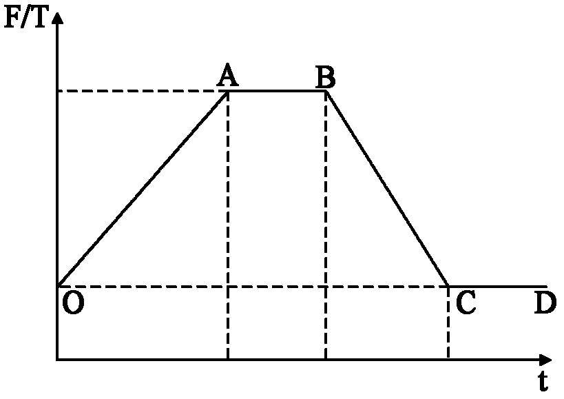
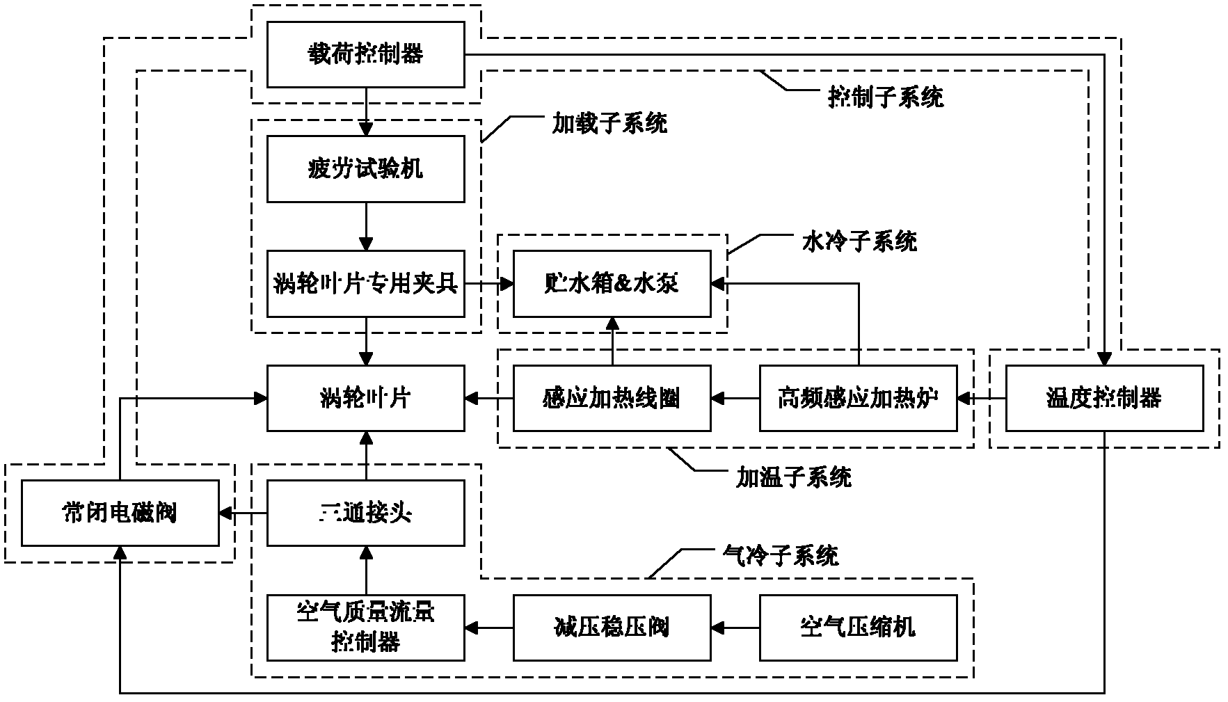
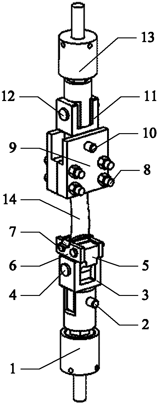
[0050] The following is a further description of the technical scheme adopted by a hollow air-cooled turbine blade thermomechanical fatigue test system of the present invention to realize the simulation of the work stress field, temperature field and load spectrum of the examination section in conjunction with the accompanying drawings. The load spectrum of the thermomechanical fatigue test of the hollow air-cooled turbine blade is as follows: figure 1 As shown, it is divided into four stages: loading (O-A), peak holding (A-B), unloading (B-C) and valley holding (C-D). The assessment section of the turbine blade is the middle section of the blade body. Through the finite element method, the working stress field and temperature field of the turbine blade examination section in the peak holding stage of the load spectrum are calculated, and this is used as the target of the stress field and temperature field simulation under the test conditions. The composition of the thermome...


PUM


Abstract

The invention discloses a thermal mechanical fatigue test system for a hollow air-cooled turbine blade, which includes a loading subsystem, a heating subsystem, an air cooling subsystem, a water cooling subsystem and a controlling subsystem, wherein the loading subsystem vertically clamps the turbine blade; the heating subsystem is horizontally placed in the middle part of the loading subsystem for heating the turbine blade; the air cooling subsystem is horizontally arranged and connected with the loading subsystem through a pipeline; the water cooling subsystem is horizontally arranged and connected with the loading subsystem and the heating subsystem through the pipeline; and the controlling subsystem is arranged at the upper part of the heating subsystem and connected with the loading subsystem, the heating subsystem and the air cooling subsystem through a cable. The thermal mechanical fatigue test system is used for simulating the working stress field, the temperature field and the loading spectrum of the examination cross section of the hollow air-cooled turbine blade. The thermal mechanical fatigue test system satisfactorily overcomes the difficulty for simulating the working stress field, the temperature field and the loading spectrum of the examination cross section of the hollow air-cooled turbine blade, and provides the technical basis and the safety guarantee for the safe and reliable working of the aero engine.

Description

(1) Technical field [0001] The invention relates to a thermomechanical fatigue test system for an aeroengine turbine blade, in particular to a thermomechanical fatigue test system for a hollow air-cooled turbine blade, which is a test device capable of simulating the stress field, temperature field and load spectrum of a turbine blade assessment section , belongs to the field of aerospace engine technology. (2) Background technology [0002] The thermomechanical fatigue (TMF) failure of gas turbine blades is one of the most important failure types during the service of aero-engines, and it is the main factor affecting the service life of engine turbine blades. At present, most thermomechanical fatigue tests for nickel-based single crystal superalloys are based on standard specimens and blade approximate specimens. However, the actual turbine rotor blades must bear centrifugal force, aerodynamic force and other loads during the working process, resulting in stretching, torsi...

Claims


Application Information

Patent Timeline
IPC IPC(8): G01M13/00
Inventor 王荣桥荆甫雷侯贵仓胡殿印樊江申秀丽
Owner BEIHANG UNIV
Learn More