Manufacturing method and structure of long-distance radio frequency identification metal product

A technology of long-distance wireless and metal products, applied in the direction of recording carriers used in machines, instruments, computer parts, etc., can solve the problems of high implementation cost, unsuitable for low-cost mass production of electronic tags, and difficult handling of contacts

Active Publication Date: 2012-07-04
RFID INTEGRATED MARKETING CO LTD
View PDF5 Cites 13 Cited by
  • Summary
  • Abstract
  • Description
  • Claims
  • Application Information

AI Technical Summary

Problems solved by technology

The distance H between the former electronic tag and the metal surface should be kept at a height of more than 2.5mm. Although this improves the reading distance of the electronic tag, it will increase the volume cost of the entire tag and reduce the bandwidth of the antenna. It does not really solve the problem. The impact of surface metal on the electronic tag antenna, so the current traditional electronic tag antenna is almost used on non-metallic surfaces, such as the design of ETC in Taiwan, China, and the general identification tag TAG
The latter, the technology of combining the slotting method with the electronic tag, will have great problems in terms of reliability and flatness, especially the joint between the chip and the metal point, due to the characteristics of metal thermal expansion and cold contraction, it will cause problems for a long time. The joints fall off, and with this design, since each piece of metal antenna must be impedance-matched with the chip (if there is no matching, it will easily cause frequency deviation or field shape changes), including the difficult handling of the joints (generally using conductive glue, Copper laying, electroplating copper, vacuum sputtering copper, etc.), using conductive glue, because it is easy to have life and temperature reliability problems, the life of conductive glue is about 2 to 5 years at room temperature, and the conductive substance in the glue is oxidized. After curing, the bonding layer between the conductive material and the material has a certain resistance value. The cumulative resistance value of many conductive materials will cause the VF value to rise, resulting in excessive frequency offset and field shape variability, resulting in difficulty in controlling the degree of control; caused by copper l

Method used


Image

  • Manufacturing method and structure of long-distance radio frequency identification metal product
  • Manufacturing method and structure of long-distance radio frequency identification metal product
  • Manufacturing method and structure of long-distance radio frequency identification metal product

Examples


Embodiment Construction

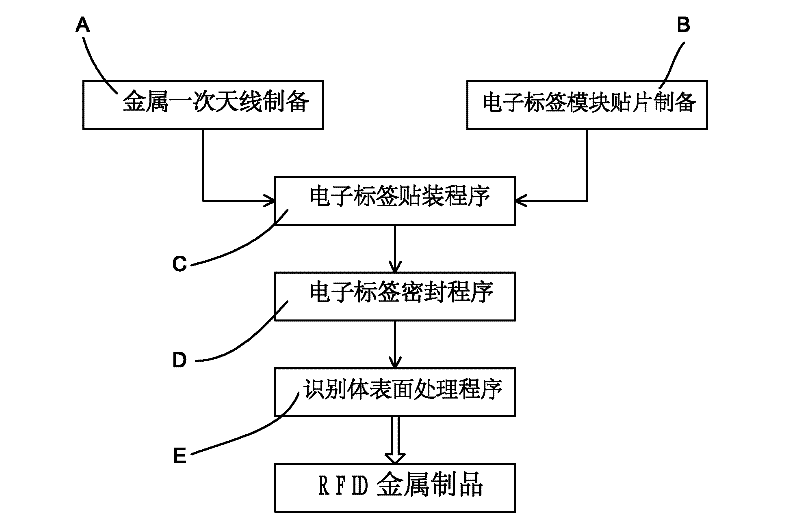
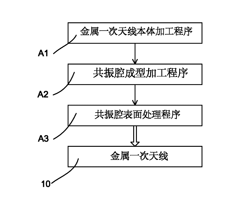
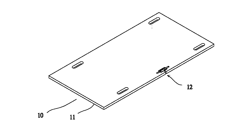
[0036] A method of manufacturing long range radio frequency identification metal products such as figure 1 , including at least one metal primary antenna preparation A, one electronic label module patch preparation B, one electronic label mounting procedure C, one electronic label sealing procedure D and one identifier surface treatment procedure E; the primary metal antenna preparation A, such as figure 2 , the metal primary antenna 10 is manufactured by a metal primary antenna body processing program A1, a resonant cavity forming processing program A2 and a resonant cavity surface treatment program A3. The metal primary antenna body processing program A1 is in the metal product On the selected metal sheet, such as image 3 , punching out the metal primary antenna body 11 of the predetermined shape of the license plate by stamping, such as figure 2 , 3 , 4. The resonant cavity forming processing procedure A2 is to punch out two inner slots 120 and an outer slot 121 in the...


PUM


Abstract

The invention discloses a manufacturing method and a structure of a long-distance radio frequency identification metal product. Ultrahigh-frequency radio frequency identification (UHF RFID) can be applied to various metal products without interference; electromagnetic waves emitted by an emitter are received by a metal primary antenna on the metal product; by utilizing a resonant cavity in the metal primary antenna and a secondary antenna of an electronic tag module patch, resonance and sensing are generated to transmit a signal to a radio frequency identification (RFID) wafer so as to achieve a long-distance reading and sending effect; when fragment cutting lines at the position of the secondary antenna are disassembled, the secondary antenna is damaged and loses efficacy; the electronic tag module patch is bound by an adhesive and sealed in the metal primary antenna; if the electronic tag module patch is disassembled, the effect that the secondary antenna is damaged and loses efficacy can also be caused, so that the metal product has an RFID function and also has an anti-copy efficacy.

Description

technical field [0001] The invention relates to a long-distance radio frequency identification metal product manufacturing method and structure which is free from metal interference, has long-distance reading and sending effects, and has anti-copy and anti-copy effects. Background technique [0002] Radio Frequency Identification (RFID) technology has been widely used in many fields such as industrial automation, commercial automation, and traffic control management. More and more researches have begun to study the ultra-high frequency (UHF) RFID system in order to realize the characteristics of the system such as long-distance, high efficiency, and low cost. Because RFID has the advantages of non-contact, low cost, high anti-counterfeiting and low cost in mass production, it has gradually replaced the traditional two-dimensional barcode. Currently on the market, radio frequency identification (RFID) is also widely used in many fields such as identification, access control,...

Claims


Application Information

Patent Timeline
IPC IPC(8): G06K19/077
Inventor 张淑如
Owner RFID INTEGRATED MARKETING CO LTD
Why Eureka
Try Eureka